Centrifugal oil purifying machine

A technology for purifying machines and oil, applied in centrifuges, centrifuges with rotating drums, etc., can solve the problems of affecting the cleanliness of oil, non-divergence, high efficiency, etc., to improve the secondary purification effect and sewage discharge capacity Strong, stable performance

Active Publication Date: 2011-09-14
WEIHAI SUOTONG ELECTROMECHANICAL EQUIP +1
View PDF6 Cites 16 Cited by
  • Summary
  • Abstract
  • Description
  • Claims
  • Application Information

AI Technical Summary

Problems solved by technology

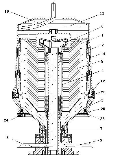
This centrifugal oil purifier uses the principle of centrifugal purification to remove pollutants greater than the specific gravity of the oil. Its advantage is that the machine not only removes 100% of free water but also has a strong effect on dissolved water while rotating at high speed. The removal ability is conducive to the extension of oil life and safe operation, and high efficiency. The disadvantages: First, if the speed of the centrifugal cylinder is increased, when the purified oil is input to the inlet of the impeller at the front end of the centrifugal cylinder, the centrifugal impeller will be left at a high speed. Rotate, on the one hand, the sucked oil rotates along the circumference under the drive of the impeller; The channel formed is constantly moving upward, and the pollutants in the oil are constantly moving towards the cylinder wall under the action of centrifugal force, and on the other hand, they are driven upward by the oil. Therefore, the pollution particles in the oil It is moving according to a helical synthetic motion trajectory, and large particles of pollutants will be attached to the cylinder wall in this interval. This interval is called the first purification area. The interval from the outflow to the outflow is called the second purification zone
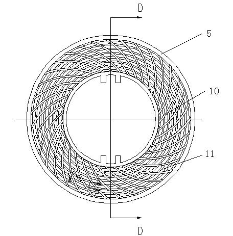
As we all know, in order to obtain a good purification effect, the centrifugal cylinder can be rotated at high speed to establish a high-speed rotating flow field. The higher the rotation speed, the smaller the particle size of the separated pollutants and the higher the purification accuracy. However, this centrifugal The disc-type guide plate in the oil purifier is made of plastic material. After increasing the speed of the centrifugal cylinder, there will be a lot of relative movement between the oil and the edge of the disc-type guide plate just before the oil enters the second purification zone. The disc guide plate rotates the liquid, the higher the speed of the disc guide plate rotating with the centrifugal cylinder, the greater the tangential velocity between the disc guide plate edge and the oil, and the greater the speed pressure, according to Bernoulli The relationship pointed out by the equation: removing the influence of the position head, the static pressure head and the velocity head at this point should be equal to the total water head. Therefore, the static pressure must decrease when the velocity pressure increases. If the static pressure at this point drops to the gas in the liquid When the pressure is separated, the gas dissolved in the oil will be separated. When the oil is about to flow into the gap of the disc guide plate, the air bubbles will be precipitated. Due to the pressure acting on the liquid, there will be air bubbles. It is called cavitation. Under the action of surrounding pressure, these bubbles will quickly "dissolve" into the oil. There are literatures that the appearance and collapse of cavitation will produce "knocking". The impact pressure of 100 atmospheres produces a "cavitation" phenomenon, which easily destroys the plastic disc guide plate, causing a large number of non-metallic pollutant particles to appear in the purified oil. Generally, the cleanliness of this oil is measured at 12 Level or so, it will show a state of non-divergence, which will seriously affect the cleanliness of the oil; second, during the centrifugal rotation of the oil, because the wall of the centrifugal cylinder is in a closed state, the solid particles, water and air with large specific gravity will be separated under the centrifugal force Under the action, it moves toward the inner wall of the centrifugal cylinder, so that many pollutants, moisture and air are attached to the inner wall of the centrifugal cylinder. After the centrifugal cylinder stops rotating, these pollutants and moisture attached to the cylinder wall lose 
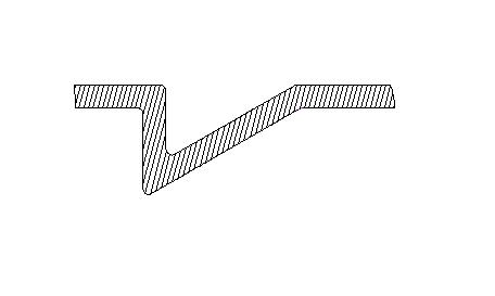
centrifugal force and are released by gravity. Under the action of the centrifugal cylinder wall and the slope between the blades of the front end cover, it flows into the dirt receiving box through the sewage pipe, so that the purification and separation effect of the oil is not obvious. Therefore, the structure of the centrifugal cylinder and the disc guide plate The material, geometric shape and surface shape are all important links to determine the purification level of the oil purifier; third, during the high-speed rotation of the centrifugal cylinder, due to the connection between the support rod and the sleeve of the rotating skeleton in the prior art Rod connection, the connecting rod and the sleeve and the support rod are in a vertical state, while the oil moves upwards in a spiral trajectory under the action of centrifugal force, and the structure of the connecting rod and the support rod is applied to the swirl process The opposite resistance of the oil in the center causes the radial partial velocity of the discharged oil to decrease, which reduces the purification effect of the oil; Fourth, because the outer surface of the front end cover is fixed with the lower half of the centrifugal cylinder, and is sealed by the sealing ring, in After the purifier has been running for a long time, the pollutants separated from the oil, some viscous substances are deposited in the gaps of the disc guide plate, which will reduce the circulation area of ​​the oil and reduce the purification effect. The front cover needs to be removed frequently Cleaning the centrifuge, this structure is very difficult to disassemble and install

Method used


Image

  • Centrifugal oil purifying machine
  • Centrifugal oil purifying machine
  • Centrifugal oil purifying machine

Examples


Embodiment Construction

[0024] Below in conjunction with accompanying drawing, the present invention is further described:

[0025] As shown in the accompanying drawings, a centrifugal oil purifier is provided with a central shaft 1, a centrifugal cylinder 2, a front end cover 3, a rotating frame 4, a disc guide plate 5, an oil collecting impeller 6, a rotating wheel 7, a driving device, Oil outlet pipe 8, oil inlet pipe 9 and oil tank, central shaft 1, centrifugal cylinder 2, front end cover 3, rotating frame 4, disc guide plate 5, oil collecting impeller 6, rotating wheel 7, oil outlet pipe 8, oil inlet pipe 9 and oil tank The structure and connection relationship are the same as those of the prior art, so I won’t go into details here. It is characterized in that the disc-type guide plate 5 is made of titanium alloy material, so as to improve the purification speed, so that the disc-type guide plate 5 has high strength and corrosion resistance. Good heat resistance, to resist the "cavitation phenom...


PUM


Abstract

The invention relates to the technical field of oil purification equipment, in particular to a centrifugal oil purifying machine. The centrifugal oil purifying machine is provided with a central shaft, a centrifugal cylinder, a front end cover, a rotating framework, a disk type guide plate, an oil collecting impeller, a driving device, an oil outlet pipe, an oil inlet pipe and an oil tank, and is characterized in that the disk type guide plate is made of titanium alloy material, involute-shaped convex edges are radially uniformly distributed on the surface of the disk type guide plate, oil-blocking convex edges are arranged between the involute-shaped convex edges, the oil-blocking convex edges are in ladder-like distribution, at least two drainage holes are arranged in the positions with large diameter below a cylinder body of the centrifugal cylinder in the centrifugal oil purifying machine, a water storage cavity is arranged above the cylinder body of the centrifugal cylinder, a drainage channel is arranged in the wall of the centrifugal cylinder, the drainage holes are communicated with the water storage cavity via the drainage channel, the water storage cavity is communicated with a water outlet guide pipe, and water sealing devices are arranged in the drainage holes. Due to the adoption of the structure, the centrifugal oil purifying machine has the advantages of novel structure, strong pollution discharge capability, safety in operation, stable performances, long service life of oil, no operation cost, no consumption of filter material, obvious separation effect and the like.

Description

technical field [0001] The invention relates to the technical field of oil purification equipment, in particular to a centrifugal oil purification machine. Background technique [0002] How to remove pollutants such as solid particles, moisture and gas in the oil is the main topic of the current system pollution control industry. At present, the means of oil pollution control mainly rely on the pressure plate oil filter and the filter screen oil filter , Vacuum plus filter screen oil filter, coalescing oil filter and other equipment. The pressure plate oil filter uses multi-layer filter paper to filter layer by layer. The advantage is that the oil filter precision is high. The disadvantage is that it can only remove solid particles in the oil, but cannot filter out the water and gas mixed in the oil. Moreover, in The filter paper needs to be replaced frequently during use, which is inconvenient to use and high in operating costs; the screen type oil filter uses a high-preci...

Claims


Application Information

Patent Timeline
Patent Type & Authority Applications(China)
IPC IPC(8): B04B5/00B04B7/00B04B7/08B04B11/02
CPCB04B7/08B04B1/08B04B7/14B04B5/005
Inventor 索和
Owner WEIHAI SUOTONG ELECTROMECHANICAL EQUIP
Why Eureka
Try Eureka