Bearing power generating configuration

A technology of bearings and generators, applied in wind power generation, bearing assembly, bearing components, etc., can solve problems such as personal injury and death

Inactive Publication Date: 2015-02-25
AB SKF
View PDF5 Cites 1 Cited by
  • Summary
  • Abstract
  • Description
  • Claims
  • Application Information

AI Technical Summary

Problems solved by technology

Bearing failure could even result in personal injury or death if coincidence occurs

Method used


Image

  • Bearing power generating configuration
  • Bearing power generating configuration
  • Bearing power generating configuration

Examples


Embodiment Construction

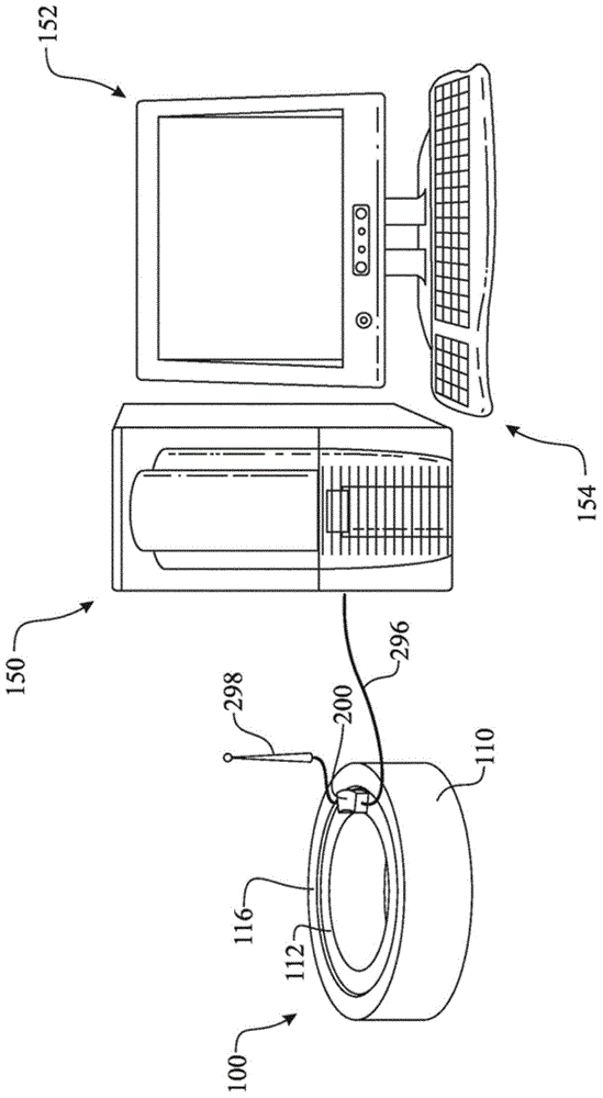
[0036] The following detailed description is merely exemplary in nature and is not intended to limit the described embodiments or the application and uses of the described embodiments. As used herein, the word "exemplary" or "exemplary" means "serving as an example, instance, or illustration." Any implementation described herein as "exemplary" or "exemplary" is not necessarily to be construed as preferred or advantageous over other implementations. All of the embodiments described below are exemplary embodiments configured to enable those skilled in the art to make or use the embodiments of the invention, and are not intended to limit the scope of the invention, which is defined by the claims. For the purposes of this description, the terms "upper", "lower", "left", "rear", "right", "front", "vertical", "horizontal" and their derivatives refer to figure 1 Inventions targeted in . Furthermore, there is no intention to be bound by any expressed or implied theory presented in t...


PUM


Abstract

A power generating bearing assembly (100) comprising a power generating subassembly (200, 300, 400) integrated into a bearing (110). The power generating subassembly (300, 400) utilizes the relative motion between a bearing inner ring (112) and a bearing outer ring (116) of the bearing (110) to generate electrical power. A sealing system (130) is attached to one of the bearings (112, 116). The power generating subassembly (300, 400) includes an electrical generator (310, 410) in operational engagement with a magnetically polarized material (324, 424). The electrical generator (310, 410) is attached to the non-sealing carrying bearing (112, 116). The magnetically polarized material (324, 424) can be attached directly to the sealing system (130) or carried by a magnetically polarized material mount ring (320). The relative motion between the rings (112, 116) engages the electrical generator (310, 410) and the magnetically polarized material (324, 424) causing a generator core (312, 412) of the electrical generator (310, 410) to create an electrical current.

Description

technical field [0001] The invention relates to a device and method for generating electricity during bearing movement. Background technique [0002] A bearing can be defined as any of various mechanical elements that restrict relative motion between two or more components to only the desired type of motion. Typically, this allows and facilitates free rotation about the longitudinal axis and / or inhibits any linear movement of the component in a direction relative to the normal to the bearing. Bearings can be broadly classified according to the motion they allow and according to their principle of operation and the direction of applied loads they can handle. [0003] Bearings experience considerable use, which causes wear on the various bearing components. Over time, bearing wear can lead to mechanical failure. Mechanical failures may affect rotational motion and / or axial linear constraints. Failure to control any of these movements can lead to catastrophic failure of the...

Claims


Application Information

Patent Timeline
Patent Type & Authority Applications(China)
IPC IPC(8): F16C41/00H02K7/18
CPCF16C41/004Y02E10/725H02K7/1846Y02E10/72
Inventor F.巴特尔J.厄斯金S.齐格勒A.C.范德哈姆
Owner AB SKF
Why Eureka
Try Eureka