An Optical System for Measuring Retroreflection Coefficient

A technology of retroreflection coefficient and optical system, applied in the measurement of scattering characteristics, etc., can solve the problems of cumbersome test process, low test accuracy, bulky volume, etc., and achieve the effect of variable incident angle and observation angle, convenient operation and small size

Active Publication Date: 2017-09-26
ANHUI UNION SAFE TECH
View PDF7 Cites 0 Cited by
  • Summary
  • Abstract
  • Description
  • Claims
  • Application Information

AI Technical Summary

Problems solved by technology

Traffic signs play an important role in traffic safety, but the devices for detecting the retroreflection coefficient of these reflective signs are far behind the actual needs
Most of the existing retroreflection coefficient detection devices are indoor desktops, which have the disadvantages of bulky, cumbersome testing process, and low testing accuracy, and their incident angle and observation angle are fixed, and their focal length is a long focal length.

Method used


Image

  • An Optical System for Measuring Retroreflection Coefficient
  • An Optical System for Measuring Retroreflection Coefficient
  • An Optical System for Measuring Retroreflection Coefficient

Examples


Embodiment Construction

[0027] The present invention will be further described below in conjunction with accompanying drawing:

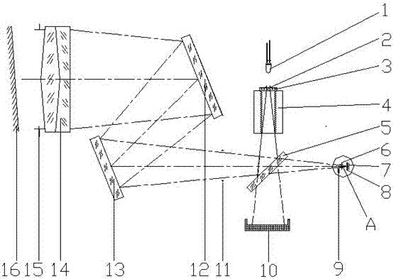
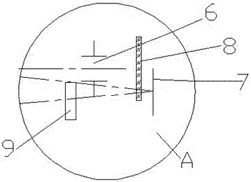
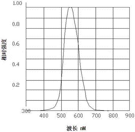
[0028] Such as Figure 1-Figure 2 The shown optical system for measuring the retroreflection coefficient includes an illumination light source, a beam splitter 5 , a mirror, an achromatic objective lens 14 , a filter 8 and a photodiode receiver 7 . The beam splitter 5 is arranged obliquely at an angle of 45 degrees below the illumination source. The reflector, the achromatic objective lens 14 , the optical filter 8 and the photodiode receiver 7 are arranged on the left and right sides of the illumination light source and the beam splitter 5 respectively. A stray light absorbing device 10 is arranged below the beam splitter 5 . Preferably, the achromatic objective lens 14 is a double-bonded achromatic objective lens with a medium focal length. The filter 8 is a vision correction filter, which corrects the visual curve. The photodiode receiver 7 is a silicon photodiode re...


PUM


Abstract

The invention relates to an optical system for measuring retroreflection coefficient, which comprises an illumination light source, a beam splitter, a mirror, an achromatic objective lens, a filter mirror and a photodiode receiver. The beam splitter is arranged below the illumination source. The reflective mirror, the achromatic objective lens, the filter mirror and the photodiode receiver are respectively arranged on the left and right sides of the illumination light source and the beam splitter. The illumination light source includes a warm white LED lamp, a light source aperture diaphragm, a soft mirror and a scattered light processing device sequentially arranged under the warm white LED lamp. The beam splitter is a transflective beam splitter, and it is obliquely arranged below the scattered light processing device. The reflector is a compound reflector, including a large reflector and a small reflector arranged in pairs. To sum up, the present invention has the characteristics of small size, high precision, convenient operation, variable incidence angle and observation angle, and the like.

Description

technical field [0001] The invention relates to the technical field of retroreflection detection, in particular to an optical system for measuring retroreflection. Background technique [0002] At present, the traffic construction is developing rapidly, and the traffic signs on the road are also becoming more and more perfect. Traffic signs play an important role in traffic safety, but the devices for detecting the retroreflection coefficient of these reflective signs are far behind the actual needs. Most of the existing retroreflection coefficient detection devices are indoor desktops, which have the disadvantages of bulky, cumbersome testing process, low testing accuracy, etc., and the incident angle and observation angle are fixed, and the focal length is a long focal length. Contents of the invention [0003] The object of the present invention is to provide an optical system for measuring the retroreflection coefficient, which has the characteristics of small size, h...

Claims


Application Information

Patent Timeline
Patent Type & Authority Patents(China)
IPC IPC(8): G01N21/47
Inventor 胡辉杨茂林唐岩艾正伟陈淮南
Owner ANHUI UNION SAFE TECH
Why Eureka
Try Eureka