Elastic support and method for temporarily supporting load by using same

A technology of elastic bearings and butterfly springs, which is applied in the preparation of pillars and building components on site, construction, etc., can solve the problems of complex operation, unrestricted support force, high maintenance cost, etc., and achieve easy operation, simple structure, and no structure. damage effect

Active Publication Date: 2015-05-06
SHANGHAI MECHANIZED CONSTR GRP
View PDF6 Cites 4 Cited by
  • Summary
  • Abstract
  • Description
  • Claims
  • Application Information

AI Technical Summary

Problems solved by technology

[0004] Aiming at the problem that conventional rigid temporary support members cannot limit the support force and adopt hydraulic jack as the support, the operation is complicated and the maintenance cost is high. The purpose of the present invention is to provide an elastic support and a method for temporarily supporting loads using The elastic support of the butterfly spring group transmits the load of the upper structure, controls the load of the temporary support, and protects the safety of the underground building structure below it

Method used


Image

  • Elastic support and method for temporarily supporting load by using same
  • Elastic support and method for temporarily supporting load by using same

Examples


Embodiment 1

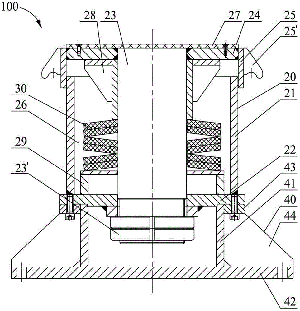
[0025] Example 1: Combining figure 1 Explain that the elastic support 100 of the present invention includes a butterfly spring support 20 and a base 40 arranged up and down and connected by bolts;

[0026] Belleville spring support 20 comprises inner sleeve 21, base plate 22 fixed on the bottom of inner sleeve 21, mandrel 23 vertically arranged in inner sleeve 21, and upper cover plate affixed to the top of mandrel 23, the core The bottom end of the shaft 23 passes through the central hole of the base plate 22 and is locked by a nut. The upper cover plate is formed by connecting the end plate 24 and the outer sleeve 25. The outer sleeve 25 is sleeved outside the inner sleeve 21 and can be moved along the inner sleeve 21. The sleeve 21 slides longitudinally relative to each other, and the upper cover plate, the inner sleeve 21 and the bottom plate 22 jointly form a closed cavity 26, and the butterfly spring group 30 arranged in the cavity 26 is sleeved on the mandrel 23; the bu...

Embodiment 2

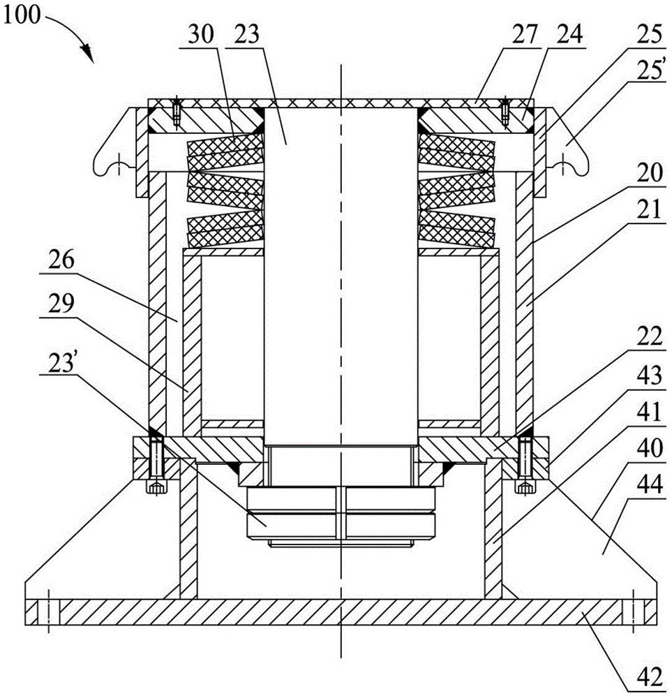
[0035] Embodiment two: different from embodiment one, as figure 2 As shown, in the present embodiment, the top of the butterfly spring group 30 is against the end plate 24 of the upper cover plate, that is to say, the adjustment frame 28 is not provided between the end plate 24 and the butterfly spring group 30, and the butterfly spring seat 29 is increased. Height can also achieve a similar effect, which will not be repeated here.

Embodiment 3

[0036] Example Three: Combining figure 1 and figure 2 Illustrate the method for utilizing the elastic bearing 100 of the present invention to temporarily support loads, and the specific steps are as follows:

[0037] S101: First calculate and determine the maximum load and maximum displacement borne by the support node, determine the specification, quantity and superimposition method of the butterfly spring according to the support stiffness, bearing capacity and deformation required by the design, assemble the elastic support 100, and pair the butterfly spring group 30 After pre-compression, tighten the nut 23' at the bottom of the mandrel 23, the purpose of pre-compressing the disc spring group 30 is to allow the disc spring group 30 to enter the working state (10% to 15% of the maximum load must be applied to the disc spring group 30). % of the pressure to make it reach the working state);

[0038] S102: Bolt the elastic support 100 to the support point, so that the load...


PUM


Abstract

The invention discloses an elastic support and a method for using the same as a temporary supporting structure, relates to the technical field of building engineering construction, and aims to solve the problems of complexity in operation and high maintenance cost caused by the fact that a conventional rigid temporary supporting member cannot limit supporting force and a hydraulic jack is used as the support. The elastic support comprises a butterfly spring bracket and a pedestal in bolted connection, wherein the butterfly spring bracket comprises an inner sleeve, a bottom plate, a spindle and an upper cover plate; the bottom plate is fixedly connected to the bottom of the butterfly spring bracket; the spindle is vertically arranged in the inner sleeve; the upper cover plate is fixedly connected to the top of the spindle; the bottom end of the spindle penetrates through the bottom plate and is locked by a nut; an outer sleeve sleeves the inner sleeve and can slide relatively along the inner wall; the upper cover plate, the inner sleeve and the bottom plate form a closed cavity; a butterfly spring set which is arranged in the cavity sleeves the spindle; the top end of the butterfly spring set is abutted against an end plate of the upper cover plate; the pedestal comprises a cylindrical fixing frame and an annular end plate; the bottom of the cylindrical fixing frame is connected with a support bottom plate; the annular end plate is connected to the top of the pedestal; the bottom end of the spindle is positioned in the inner cavity of the cylindrical fixing frame; the bottom plate of the butterfly spring bracket is in bolted connection with the annular end plate of the pedestal.

Description

technical field [0001] The invention relates to the technical field of civil engineering construction, in particular to an elastic bearing and a method for temporarily supporting loads using the elastic bearing. Background technique [0002] Building steel structures, especially long-span steel structures, often use steel pipe members to temporarily support the upper steel structure during construction. After the upper steel structure is formed as a whole, the steel pipes are cut off by gas cutting to reduce the original height, so as to achieve the purpose of unloading. These temporary support members are then removed. During construction, the forces transmitted from the upper steel structure to these temporary support members are very large. When building long-span steel structures above subways or other underground structures, excessive forces on temporary support members may affect the safety of underground structures. In this case, large-tonnage hydraulic jacks are of...

Claims


Application Information

Patent Timeline
Patent Type & Authority Applications(China)
IPC IPC(8): E04G25/04
Inventor 周锋吴金山郑祥杰吴欣之郁政华李璐毕伟麟孙继辉
Owner SHANGHAI MECHANIZED CONSTR GRP
Why Eureka
Try Eureka