Low noise and high pressure differential regulating valve

A technology of regulating valve and high pressure difference, applied in the direction of lift valve, valve detail, safety valve, etc., can solve the problems of impossible to reduce noise and cavitation, unsuitable single-seat regulating valve, leakage of regulating valve packing, etc., to reduce leakage volume, reducing the probability of cavitation and cavitation, and reducing the effect of output force

Active Publication Date: 2018-01-02
上海铂嘉阀门有限公司
View PDF6 Cites 0 Cited by
  • Summary
  • Abstract
  • Description
  • Claims
  • Application Information

AI Technical Summary

Problems solved by technology

[0002] In industrial automation control, it is often necessary to use regulating valves to control flow, temperature, and pressure; as far as the current fine and small regulating valves are concerned, due to insufficient standardization and modularization, the operating pressure difference is low and the versatility is poor.
In the prior art, the main problems are: the single-seat adjustment is a single-seat seal, and the valve core is in an unbalanced form. When the pressure before the valve is much greater than the pressure after the valve, a large gap will be formed above and below the valve core. Large unbalanced force, the regulating valve needs a large driving source to overcome the unbalanced force generated by the medium, so the single-seat regulating valve is not suitable for the working condition of high pressure difference, while the cage balance regulating valve is on the upper sleeve The barrel has flow holes, so it is not possible to reduce noise and cavitation under high differential pressure
On the other hand, when using the existing control valve, it is unavoidable that the filling of the control valve leaks, and the dust and debris in the air are easily brought into the stuffing box with the movement of the valve stem. can quickly cause the stuffing box seal to be breached

Method used


Image

  • Low noise and high pressure differential regulating valve
  • Low noise and high pressure differential regulating valve
  • Low noise and high pressure differential regulating valve

Examples


Embodiment Construction

[0014] The low-noise and high-pressure differential regulating valve of the present invention will be described below in conjunction with the accompanying drawings.

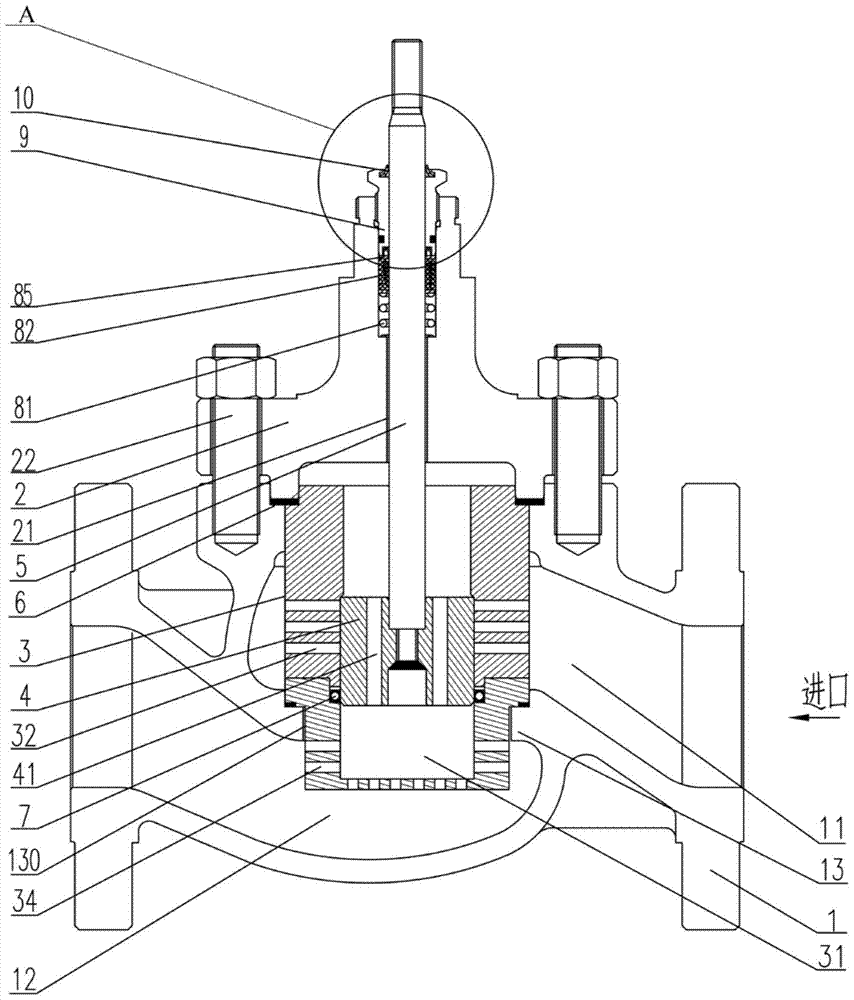
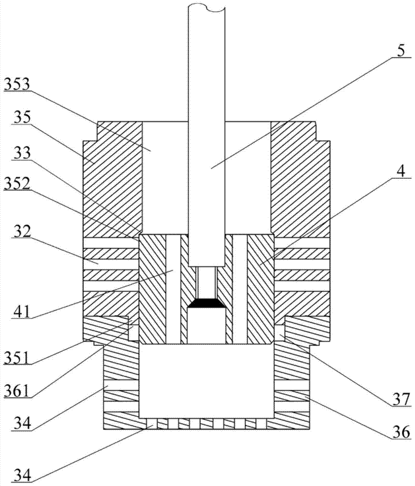
[0015] Such as figure 1 As shown, the low-noise high-pressure differential regulating valve of the present invention includes a valve body 1, a valve cover 2, a sleeve 3, a valve core 4 and a valve stem 5, wherein the valve cover 2 is connected to the On the top of the valve body 1, a through hole 130 is opened on the partition 13 between the inlet cavity 11 and the outlet cavity 12 of the valve body, so that the sleeve 3 is clamped therein, and the sleeve 3 against the valve cover 1, on the upper part of the side wall surface of the sleeve 3, there are a plurality of first-type adjustment holes 32 communicating with the valve body inlet cavity 11 and the sleeve cavity 31, The lower part of the side wall of the sleeve and the bottom surface of the sleeve are respectively opened with a plurality of second-type ad...


PUM


Abstract

The invention provides a low-noise high-pressure-difference adjusting valve which comprises a valve body, a valve cover, a sleeve, a valve element and a valve rod. The valve cover is connected to the top of the valve body through bolts, the sleeve is clamped between the valve cover and the valve body, a plurality of first-kind adjusting holes are formed in the upper portion of the side wall of the sleeve, a plurality of second-kind adjusting holes are formed in the lower portion of the side wall of the sleeve and the bottom face of the sleeve, the valve element is arranged in an inner cavity of the sleeve and can vertically move in the inner cavity of the sleeve, so that the low-noise high-pressure-difference adjusting valve is closed or opened, a plurality of pressure balance holes are formed in the valve element in the axial direction of the valve element, and the valve rod penetrates through a center through hole in the valve cover and is connected with the valve element. The low-noise high-pressure-difference adjusting valve is simple, compact and reasonable in structure, small in size and light, and has the advantage of being capable of bearing a high pressure difference and a high leakage level under the condition of the same drive source.

Description

technical field [0001] The invention relates to a valve, especially a low-noise and high-pressure differential regulating valve. Background technique [0002] In industrial automation control, it is often necessary to use regulating valves to control flow, temperature, and pressure; as far as the current fine and small regulating valves are concerned, due to insufficient standardization and modularization, the operating pressure difference is low and the versatility is poor. In the prior art, the main problems are: the single-seat adjustment is a single-seat seal, and the valve core is in an unbalanced form. When the pressure before the valve is much greater than the pressure after the valve, a large gap will be formed above and below the valve core. Large unbalanced force, the regulating valve needs a large driving source to overcome the unbalanced force generated by the medium, so the single-seat regulating valve is not suitable for the working condition of high pressure d...

Claims


Application Information

Patent Timeline
Patent Type & Authority Patents(China)
IPC IPC(8): F16K17/20F16K47/02F16K41/02
CPCF16K1/00F16K1/52F16K27/08F16K41/02F16K47/02F16K47/023
Inventor 王永茂
Owner 上海铂嘉阀门有限公司
Why Eureka
Try Eureka