Hospital ward ventilation structure

A ward and hospital technology, applied in the field of hospital ward ventilation structure, can solve problems such as the inability to achieve automatic ventilation.

Inactive Publication Date: 2015-06-03
SHAANXI DONGXIAN YONGYI ELECTROMECHANICAL TECH
View PDF0 Cites 1 Cited by
  • Summary
  • Abstract
  • Description
  • Claims
  • Application Information

AI Technical Summary

Problems solved by technology

[0002] The current ventilation of hospital wards generally relies on artificial ventilation, and automatic ventilation cannot be realized.

Method used


Image

  • Hospital ward ventilation structure

Examples


Embodiment Construction

[0009] The present invention will be described in detail below in conjunction with the accompanying drawings.

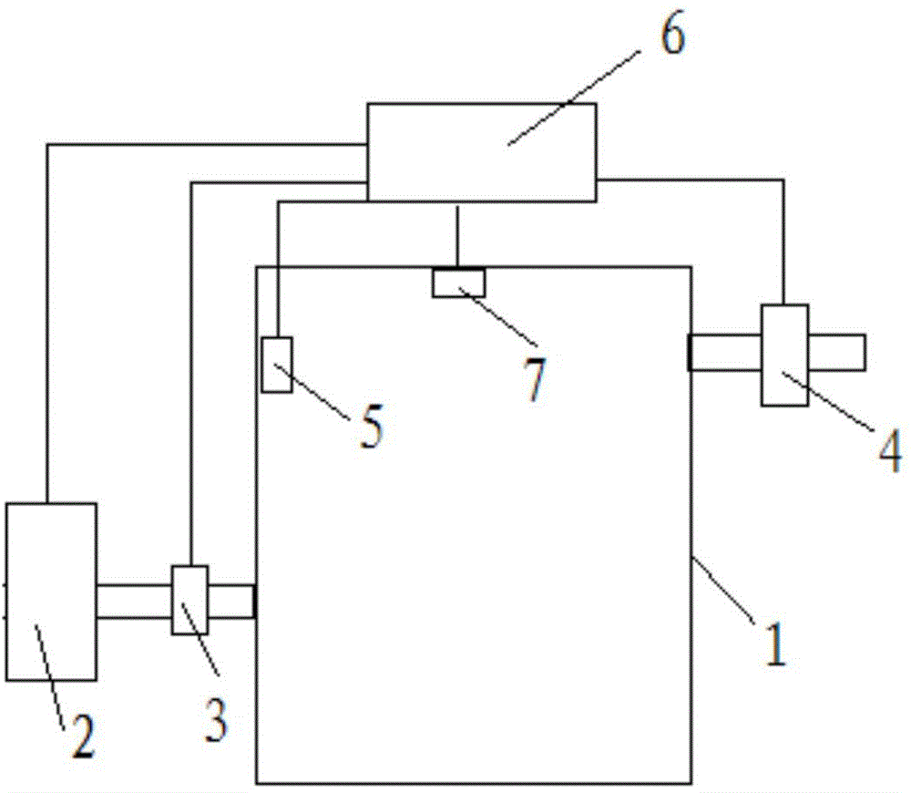
[0010] With reference to the accompanying drawings, a ventilation structure for a hospital ward includes a ward 1, the air inlet of the ward 1 is connected to the air pump 2 through an air inlet pipe, and a heating device 3 is also arranged on the air inlet pipe, and the air outlet of the ward 1 passes through the air outlet pipe and the air pump 2. The exhaust device 4 is connected, the top of the ward 1 is provided with a temperature sensor 5 and a humidity sensor 7, the temperature sensor 5, the humidity sensor 7 are connected to the input of the controller 6, and the output of the controller 6 is respectively connected to the air pump 2, the heating device 3, the exhaust The control end of wind device 4 is connected.

[0011] The working principle of the present invention: the controller 6 judges according to the real-time data of the temperature sensor 5 and the...


PUM


Abstract

A hospital ward ventilation structure comprises a ward. An air inlet of the ward is connected with an air pump through an air inlet pipe, a heating device is arranged on the air inlet pipe, an air outlet of the ward is connected with an air exhausting device through an air outlet pipe, a temperature sensor and a humidity sensor are arranged at the top of the ward and connected with input of a controller, output of the controller is respectively connected with control ends of the air pump, the heating device and the air exhausting device, the controller performs discrimination according to preset values, the air pump and the heating device can be started to input warm and wet gas to the ward once the temperature or humidity does not meet the requirement of the ward, and automatic ventilation can be realized by the aid of the air exhausting device.

Description

technical field [0001] The invention relates to a ventilation structure for a hospital ward. Background technique [0002] Ventilation in the hospital wards generally depends on artificial ventilation, and automatic ventilation cannot be realized. Contents of the invention [0003] In order to overcome the above-mentioned defects in the prior art, the object of the present invention is to provide a ventilation structure for a hospital ward, which can realize automatic ventilation. [0004] In order to achieve the above object, technical scheme of the present invention is: [0005] A ventilation structure for a hospital ward, including a ward 1, the air inlet of the ward 1 is connected to an air pump 2 through an air intake pipe, a heating device 3 is also provided on the air intake pipe, and the air outlet of the ward 1 passes through an air outlet pipe and an exhaust device 4 connection, the top of the ward 1 is provided with a temperature sensor 5 and a humidity sensor...

Claims


Application Information

Patent Timeline
Patent Type & Authority Applications(China)
IPC IPC(8): F24F7/007F24F11/02
CPCF24F7/007F24F11/30F24F11/70F24F2110/10F24F2110/20
Inventor 杜录贤
Owner SHAANXI DONGXIAN YONGYI ELECTROMECHANICAL TECH
Why Eureka
Try Eureka