A Rotary Gas Distribution Structure of Ring-type Series Cylinder Groups

A rotary gas distribution and cylinder bank technology, which is applied to combustion engines, machines/engines, internal combustion piston engines, etc., can solve the problems that the valve structure cannot realize intake and exhaust, etc., and achieve low vibration and noise and fast response speed Effect

Active Publication Date: 2021-08-13
NAT UNIV OF DEFENSE TECH
View PDF0 Cites 0 Cited by
  • Summary
  • Abstract
  • Description
  • Claims
  • Application Information

AI Technical Summary

Problems solved by technology

[0003] However, the engine cylinders adopt a ring-shaped series layout, which brings about the problem that the cylinders rotate around the main shaft of the engine in one direction, and the traditional valve structure cannot be used to realize the processes of intake and exhaust.

Method used


Image

  • A Rotary Gas Distribution Structure of Ring-type Series Cylinder Groups
  • A Rotary Gas Distribution Structure of Ring-type Series Cylinder Groups
  • A Rotary Gas Distribution Structure of Ring-type Series Cylinder Groups

Examples


Embodiment Construction

[0028] The present invention will be further described in detail below with reference to the accompanying drawings and specific embodiments.

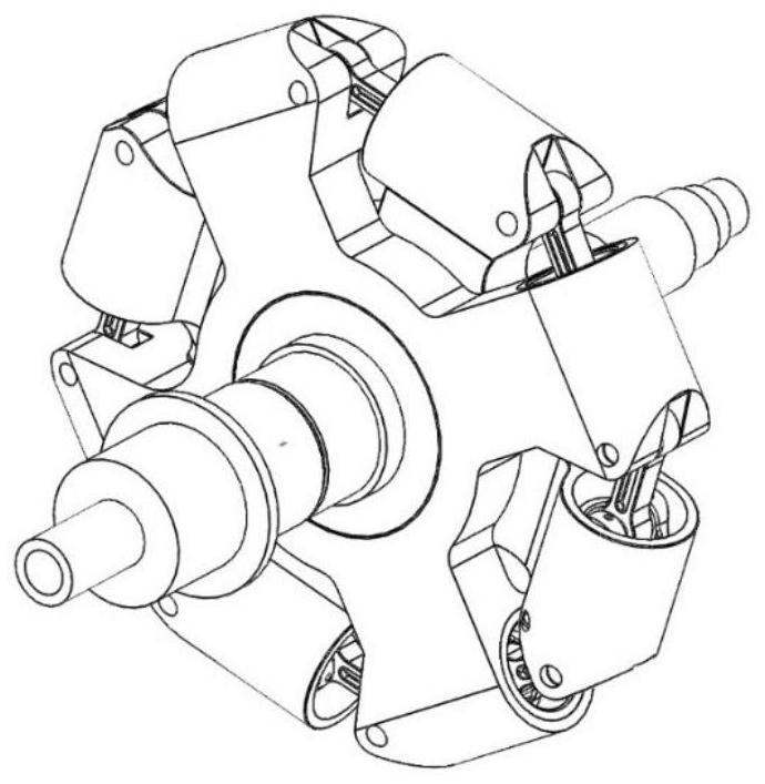
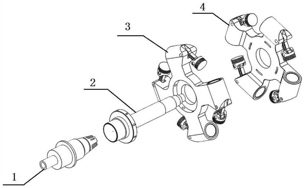
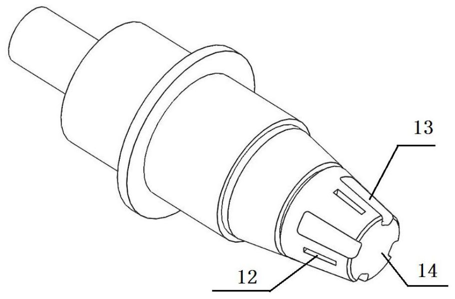
[0029] like Figure 1 to Figure 8 As shown, the present invention discloses a rotary gas distribution structure of an annular series cylinder group, comprising a gas distribution shaft 1, a rotary gas distribution bushing 2, a main rotor 3, a secondary rotor 4, a gas distribution shaft 1 and a rotary gas distribution bushing 2 Coaxial nesting installation, the main rotor 3 and the auxiliary rotor 4 are combined and sleeved on the rotary gas distribution shaft sleeve 2, the gas distribution shaft 1 is provided with an air supply channel 11, and the rotary gas distribution shaft sleeve 2 is provided with an exhaust channel 21 , a plurality of air inlets 12 and a plurality of exhaust ports 13 are arranged along the circumferential direction of the peripheral wall at the junction of the gas distribution shaft 1 and the rotating gas distribu...


PUM


Abstract

The invention discloses a rotary gas distribution structure of an annular series cylinder group, which includes a gas distribution shaft, a rotary gas distribution shaft sleeve, a main rotor and an auxiliary rotor, the gas distribution shaft and the rotary gas distribution shaft sleeve are coaxially nested and installed, the main rotor and The auxiliary rotor assembly is set on the rotary air distribution shaft sleeve. There is an air supply channel in the air distribution shaft, and an exhaust channel in the rotary air distribution shaft sleeve. There are a number of air inlets and air outlets in the circumferential direction, the air inlets communicate with the air supply passage, the exhaust outlets communicate with the exhaust passage, and the mating surface of the rotating air distribution shaft sleeve and the air distribution shaft is along the circumferential direction A number of first air ports and a number of second air ports are provided, and the air intake port, the exhaust port, the first air port and the second air port are aligned alternately with the rotation of the rotating valve sleeve, so as to realize the air exchange of each cylinder. The invention can realize high-efficiency, reliable, stable and automatic ventilation of the cylinder.

Description

technical field [0001] The invention mainly relates to the technical field of piston engines, in particular to a rotary gas distribution structure of annular series cylinder groups. Background technique [0002] The reciprocating piston engine is simple in principle and mature in technology, and has been widely used in production and life. However, limited by the characteristics of the reciprocating motion of the piston and the configuration of the traditional crank connecting rod mechanism, it is difficult for the traditional reciprocating piston engine to significantly improve the power density and maximum output power. In order to improve the power density and maximum output power of the engine, a feasible method is to arrange multiple cylindrical cylinders with parallel axes in series along the same circumferential direction, and realize the reciprocating motion of the piston relative to the cylinder through a specially configured differential mechanism. In addition, th...

Claims


Application Information

Patent Timeline
Patent Type & Authority Patents(China)
IPC IPC(8): F02B57/04
CPCF02B57/04
Inventor 徐海军杨聪楠潘迪博张雷王文浩唐源江
Owner NAT UNIV OF DEFENSE TECH
Why Eureka
Try Eureka