Clamp for elongated workpiece with outer contour needing to be milled

A technology for elongated workpieces and outer contours, applied in the direction of manufacturing tools, metal processing machinery parts, clamping, etc., can solve the problems of fixture damage, high labor intensity of workers, and long processing time, so as to avoid bending or deformation and improve operation Safety and the effect of ensuring machining accuracy

CN104875043AActive Publication Date: 2015-09-02FOSHAN PRATIC CNC SCI & TECH
10 Cites 7 Cited by

Patent Information

Authority / Receiving Office
CN · China
Patent Type
Applications(China)
Current Assignee / Owner
Publication Date
2015-09-02

Smart Images

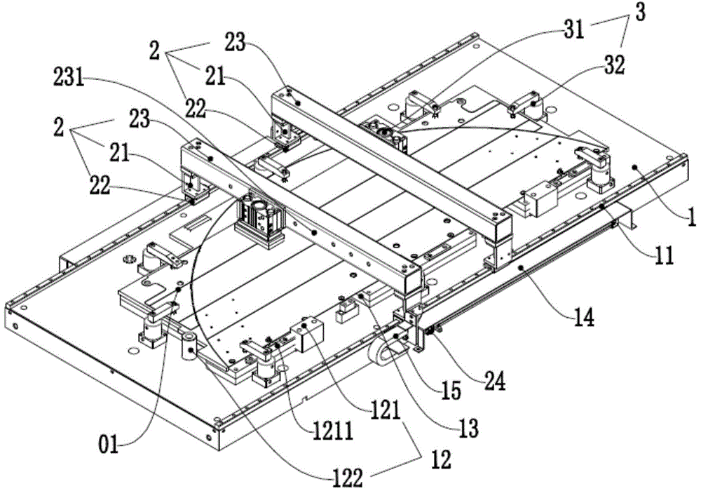
  • Figure 1
    Figure 1
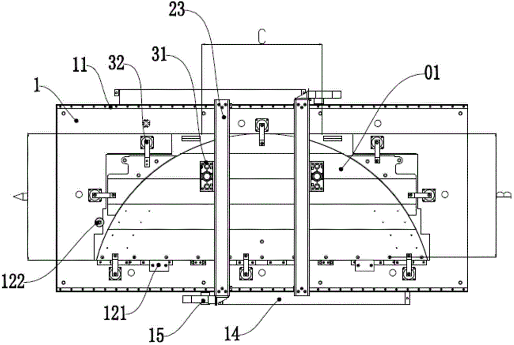
  • Figure 2
    Figure 2
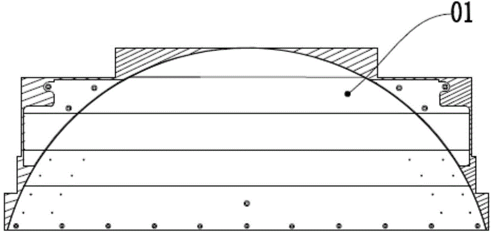
  • Figure 3
    Figure 3
Patent Text Reader

Abstract

The invention discloses a clamp for an elongated workpiece with an outer contour needing to be milled. The clamp comprises a base, a moving gantry device, a positioning device and a control system, wherein a transverse guide rail is mounted at each of the upper and lower edges of the base; limiting devices used for limiting a workpiece blank are arranged on the upper surface of the base at intervals according to the shape of the outer contour of the workpiece blank needing to be machined; a gantry frame structure moves along the transverse guide rails under the control of a gantry frame cylinder; the positioning device comprises a pressing-down positioning device used for pressing down the middle of the workpiece blank and a plurality of rotatable angle positioning devices used for pressing down the outer contour of the workpiece blank; the control system controls the movement of the moving gantry device according to the machining movement locus of a tool and controls the loosening of one or more positioning devices in the positioning devices to avoid a tool path. The invention provides the clamp for the elongated workpiece with the outer contour needing to be milled, the machining efficiency is improved, the machining path of the tool is avoided, the operation safety is improved, and the machining precision is high.
Need to check novelty before this filing date? Find Prior Art

Description

technical field

[0001] The invention relates to the field of machining fixtures, in particular to a fixture for a long workpiece whose outer contour needs to be milled. Background technique

[0002] Existing workpiece processing that requires milling of the outer contour often requires multiple manual assembly and disassembly of the workpiece pressing block, which takes a long time to process, high cost, and lacks operational safety, and generally only presses down around the workpiece. There is no pressing effect on the middle part of the workpiece, and the vibration generated by milling of the large workpiece will be transmitted to the entire workpiece during processing, so that the workpiece cannot be processed smoothly, and the machining accuracy is not high, and the middle part of the large workpiece without compression is prone to bulge In addition, when the tool is processed to the predetermined outer contour area of ​​the workpiece and the worker forgets to remove th...

Examples

Embodiment Construction

[0026] The technical solutions of the present invention will be further described below in conjunction with the accompanying drawings and through specific implementation methods.

[0027] A fixture for a long workpiece whose outer contour needs to be milled, comprising a base 1, a moving gantry device 2, a positioning device 3 and a control system;

[0028] The upper and lower sides of the base 1 are respectively equipped with a transverse guide rail 11, and the upper surface of the base 1 is provided with spacers 12 for limiting the blank workpiece 01 at intervals according to the outer contour shape of the blank workpiece 01 to be processed;

[0029] The mobile gantry device 2 includes two uprights 21, the uprights 21 are respectively symmetrically installed on the horizontal guide rails 11 on the upper and lower sides of the base 1 through the sliders 22, and the vertical fixed beams are installed between the two uprights 21. 23 connection, the two columns 21 and the fixed ...