MOM capacitor and capacitance adjusting method

An adjustment method and capacitor technology, applied in the field of capacitors, can solve problems such as inability to achieve adjustment, and achieve the effect of saving adjustment costs and accurate analog circuits

Active Publication Date: 2015-09-23
WUHAN XINXIN SEMICON MFG CO LTD
View PDF5 Cites 5 Cited by
  • Summary
  • Abstract
  • Description
  • Claims
  • Application Information

AI Technical Summary

Problems solved by technology

However, these methods can only control the capacitance value of the MOM capacitor within a range of 10%, but cannot achieve finer adjustment.

Method used


Image

  • MOM capacitor and capacitance adjusting method
  • MOM capacitor and capacitance adjusting method
  • MOM capacitor and capacitance adjusting method

Examples


Embodiment 1

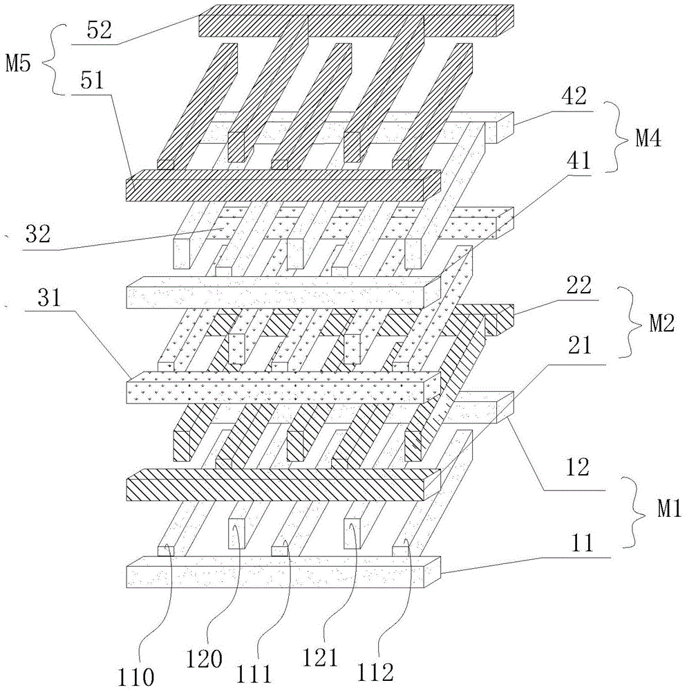
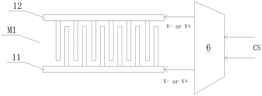
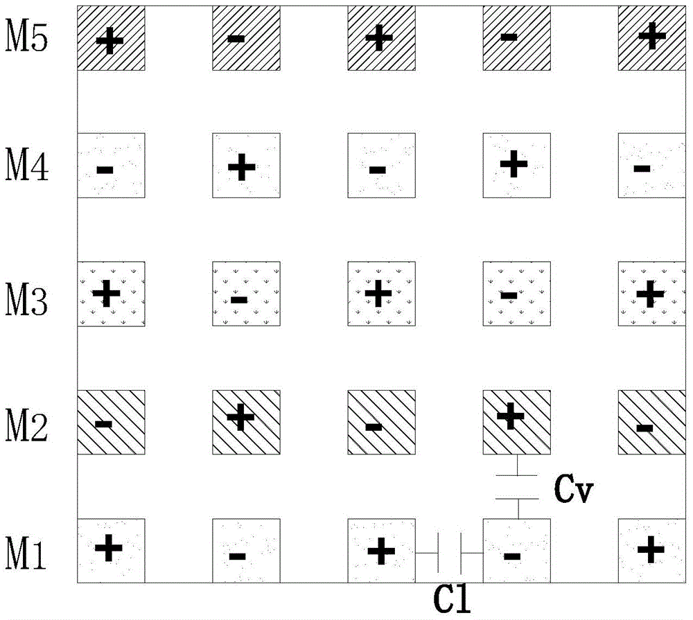
[0038] Such as image 3As shown, the first electrode 11 applied to the first metal layer M1 has a positive voltage, and the second electrode 12 has a negative voltage, so that the positive and negative polarities of each electrode finger of the first metal layer M1 are shown from left to right in the figure. Positive, negative, positive, negative, positive. A negative voltage is applied to the first electrode 21 of the second metal layer M2, and a positive voltage is applied to the second electrode 22, so that the positive and negative polarities of each electrode finger of the second metal layer M2 are shown as negative and positive from left to right in the figure. , negative, positive, negative. A positive voltage is applied to the first electrode 31 of the third metal layer M3, and a negative voltage is applied to the second electrode 32, so that the positive and negative polarities of each electrode finger of the third metal layer M3 are shown as positive and negative fr...

Embodiment 2

[0041] Such as Figure 4 As shown, the first electrode 11 applied to the first metal layer M1 has a positive voltage, and the second electrode 12 has a negative voltage, so that the positive and negative polarities of each electrode finger of the first metal layer M1 are shown from left to right in the figure. Positive, negative, positive, negative, positive. A positive voltage is applied to the first electrode 21 of the second metal layer M2, and a negative voltage is applied to the second electrode 22, so that the positive and negative polarities of each electrode finger of the second metal layer M2 are shown as positive and negative from left to right in the figure. , positive, negative, positive. A positive voltage is applied to the first electrode 31 of the third metal layer M3, and a negative voltage is applied to the second electrode 32, so that the positive and negative polarities of each electrode finger of the third metal layer M3 are shown as positive and negative ...

Embodiment 3

[0044] Such as Figure 5 As shown, the first electrode 11 applied to the first metal layer M1 has a positive voltage, and the second electrode 12 has a negative voltage, so that the positive and negative polarities of each electrode finger of the first metal layer M1 are shown from left to right in the figure. Positive, negative, positive, negative, positive. A negative voltage is applied to the first electrode 21 of the second metal layer M2, and a positive voltage is applied to the second electrode 22, so that the positive and negative polarities of each electrode finger of the second metal layer M2 are shown as negative and positive from left to right in the figure. , negative, positive, negative. A positive voltage is applied to the first electrode 31 of the third metal layer M3, and a negative voltage is applied to the second electrode 32, so that the positive and negative polarities of each electrode finger of the third metal layer M3 are shown as positive and negative ...


PUM


Abstract

The invention relates to the capacitor field, and especially relates to a MOM capacitor and a capacitance adjusting method; a first electrode and a second electrode of each metal layer are connected with a voltage switch; positive and negative polarities of voltage implemented by the voltage switch and applied to the first and second electrodes of each metal layer can be controlled, so the positive and negative polarities of a first electrode interdigital connected with one side of the first electrode and a second electrode interdigital connected with one side of the second electrode can be changed, and positive and negative polarities of each electrode interdigital in a row direction can be alternately arranged at intervals, positive and negative polarities of each electrode interdigital in a column direction can be mixedly arranged, thus finely adjusting the capacitance of the MOM capacitor. The method saves capacitance adjusting cost, so difference between an adjusted capacitance value of the MOM capacitor and a target value is smaller than 5%, and a simulation circuit can be more accurate.

Description

technical field [0001] The invention relates to the field of capacitors, in particular to an MOM capacitor and a capacitance adjustment method. Background technique [0002] Capacitors are important components in integrated circuits and are widely used in various chips. With the continuous improvement of semiconductor integrated circuit manufacturing technology, the performance of semiconductor devices is also continuously improved. How to control the capacitance of capacitors to accurately control analog circuits in the process of increasing the integration level of integrated circuits has become an important issue. [0003] During the chip production process, the variation of the capacitance value of the MOM (metal-oxide-metal) capacitor is limited within 10%. But this is not enough to optimize an analog circuit design that requires more precise control of the capacitance value of the MOM capacitor. [0004] In the prior art, there is no low-cost method for finely adjus...

Claims


Application Information

Patent Timeline
Patent Type & Authority Applications(China)
IPC IPC(8): H01L23/522
Inventor 鞠韶复
Owner WUHAN XINXIN SEMICON MFG CO LTD
Why Eureka
Try Eureka