a stealth device

A technology of stealth equipment and condensing lens, which is applied in the directions of optical components, optics, instruments, etc., can solve the problems of reducing the stealth effect, etc., and achieve the effect of low manufacturing difficulty, simple structure and good stealth effect.

Active Publication Date: 2017-12-12
湖州佳灏信息技术有限公司
View PDF5 Cites 1 Cited by
  • Summary
  • Abstract
  • Description
  • Claims
  • Application Information

AI Technical Summary

Problems solved by technology

The path layout of the optical fiber and the space occupied make stealth a huge amount of optical fiber arrangement work, and the stealth effect is greatly reduced

Method used


Image

  • a stealth device

Examples


Embodiment Construction

[0015] Typical implementations of the present invention will be described below in conjunction with specific drawings.

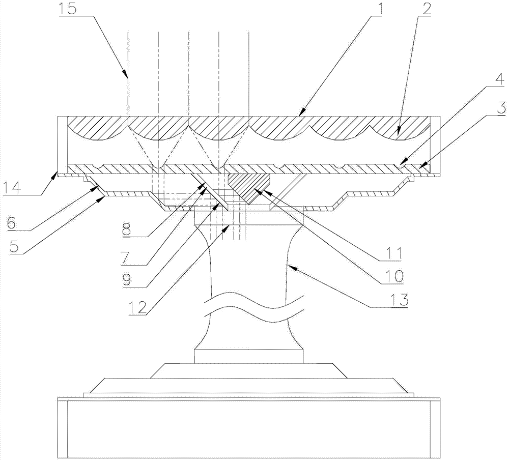
[0016] Such as figure 1 Shown:

[0017] The present invention is achieved in the following ways:

[0018] A stealth device, mainly composed of two sets of identical condenser lenses (1), parallel light lenses (3), edge reflectors (5), double-sided reflectors (7), center reflectors (10), and light-collecting blocks (12), fixed piece (14) and an optical fiber (13) form; Connect with optical fiber (13) between two covers.

[0019] Focusing lens (1), parallel light lens (3), light collecting block (12) and optical fiber (13) are all made of light-transmitting material; There are some convex lenses (2) on the focusing lens (1), each convex lens ( The edges of 2) are connected; the parallel light lens (3) has a concave lens (4) corresponding to the convex lens (2), and the focus of the concave lens (4) coincides with the focus of the convex lens (2); on the edg...


PUM


Abstract

The invention relates to the technical field of designing optical equipment, in particular to a stealth equipment. It is mainly composed of two sets of identical condenser lenses, parallel light lenses, edge reflectors, double-sided reflectors, center reflectors, light collecting blocks, fixing blocks and an optical fiber. The two sets are connected by optical fiber. The light irradiated on the edge area of ​​the condenser lens enters from one side of the condenser lens perpendicular to the condenser lens, is focused by the convex lens, and then exits through the concave lens. After multiple reflections, it is shot down into the light collecting block and optical fiber. The light propagates along the optical fiber to the components consistent with the above-mentioned light propagation path, and finally exits from the condenser lens. The invention has the characteristics of simple structure and low manufacturing difficulty. There is no need for a huge number of optical fibers, only one optical fiber is needed to realize the propagation of light, so it has a better stealth effect.

Description

technical field [0001] The invention relates to the technical field of designing optical equipment, in particular to a stealth equipment. Background technique [0002] The stealth technology used in the stealth cloak in the prior art mainly utilizes the characteristic that the light can change the propagation direction in the optical fiber. There is a problem in that a huge number of optical fibers are required. The total cross-sectional area of ​​the optical fiber is generally larger than the object to be concealed. The path layout of optical fibers and the space occupied make stealth a huge amount of optical fiber arrangement work, and the stealth effect is greatly reduced. Contents of the invention [0003] Aiming at the technical problems mentioned in the prior art, the present invention provides a stealth device. [0004] The present invention is achieved in the following ways: [0005] A stealth device, mainly composed of two sets of identical condenser lenses (1...

Claims


Application Information

Patent Timeline
Patent Type & Authority Patents(China)
IPC IPC(8): G02B17/08
Inventor 林雅洁
Owner 湖州佳灏信息技术有限公司
Why Eureka
Try Eureka