Novel probe body and machining method thereof

A processing method and probe body tube technology, applied in the direction of instruments, measuring heat, measuring devices, etc., can solve the problem that it is difficult to ensure the perpendicularity between the columnar body and the base of the probe body, the probe body is difficult to meet the design parameter requirements, and the influence of the probe Body tube stability and other issues, to achieve the effect of good processing effect, good angle requirements, and convenient production

Inactive Publication Date: 2015-10-21
NINGBO CRRC TIMES TRANSDUCER TECH CO LTD
View PDF5 Cites 0 Cited by
  • Summary
  • Abstract
  • Description
  • Claims
  • Application Information

AI Technical Summary

Problems solved by technology

Then the processed blank is cut, and then turned to process the cylindrical structure of the probe body tube at one end of the probe body base. In the process of cutting and turning the cylindrical structure of the probe body tube, it is necessary to A large amount of processing materials are cut off from the blank, and the waste generated can no longer be used, and the cost is very expensive
At the same time, with the lengthening of the probe body tube, this processing method is more difficult. For example, it is difficult to ensure the perpendicularity between the processed columnar body and the probe body base during processing, and it is very difficult to install during use.
In addition, the processed columnar body structure needs to be further processed to form the probe body tube, that is, a blind hole is drilled from the base of the probe body to the inside of the columnar body. During the drilling process, it is easy to be deflected, which will cause the probe to The wall thickness of the body tube is uneven, and it is difficult to find the uneven wall thickness, which directly affects the stability of the probe body tube during use.
It can be seen that the probe body produced by this integrated processing method is difficult to meet the design parameter requirements, and the processing accuracy cannot be guaranteed

Method used


Image

  • Novel probe body and machining method thereof
  • Novel probe body and machining method thereof
  • Novel probe body and machining method thereof

Examples


Embodiment Construction

[0027] The present invention will be further described in detail below in conjunction with the accompanying drawings and embodiments.

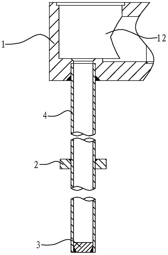
[0028] Such as Figure 1 to Figure 6 As shown, the novel probe body in this embodiment includes a probe body base 1 , a probe body tube 4 , a step body 2 and a plug 3 .

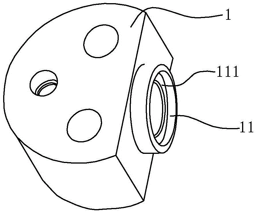
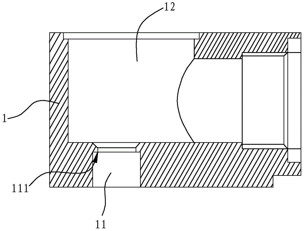
[0029] The probe body base 1 has an accommodating cavity 12 , and the probe body base 1 is also provided with a mounting hole 11 communicating with the accommodating cavity 12 , and the peripheral wall at the inner end of the mounting hole 11 has an inner shoulder 111 .

[0030] The probe body tube 4 is a hollow tube with an axial through hole, the first end of the probe body tube 4 is installed in the installation hole 11 by sealing welding, and the first end of the probe body tube 4 is against the inner The installation position of the probe body tube 4 in the installation hole 11 is limited on the shoulder 111, so as to ensure that the length of the probe body tube 4 left...


PUM


Abstract

The invention relates to a novel probe body. The novel probe body comprises a probe body base, a probe body pipe connected to the probe body base, and a plug connected into the probe body pipe. The novel probe body is reasonable in structure, convenient to assemble, high in production accuracy and low in production cost. The invention further relates to a machining method of the novel probe body. Firstly, the probe body base, the plug and the probe body pipe forming the probe body are machined, then, the probe body is welded to the probe body base, the plug is welded to the end of the probe body pipe, and finally welding surfaces are turned. The machining method of the novel probe body is low in machining difficulty, waste generated in the machining process can be effectively reduced, production cost is reduced, and meanwhile the requirement for accuracy of design parameters of the probe body can be effectively guaranteed.

Description

technical field [0001] The invention relates to a novel sensor probe body, and also relates to a processing method for the sensor probe body. Background technique [0002] The temperature sensor is an important sensing part of the locomotive measurement and control system, mainly used to monitor the temperature of the traction motor. As the main part of the temperature sensor, the probe body mainly includes the probe body base and the probe body tube connected to the probe body base. With the continuous deepening of the monitoring position, in order to ensure the normal operation of the thermal element, the length of the probe body tube Corresponding lengthening is required, and a step body is generally arranged on the corresponding probe body tube in the circumferential direction. In the prior art, the probe body is processed in an integral processing method. That is to say, the processing blank with larger volume is used, and the processing blank is machined to process t...

Claims


Application Information

Patent Timeline
Patent Type & Authority Applications(China)
IPC IPC(8): B23P15/00G01K1/00
CPCB23P15/00G01K1/00
Inventor 陈竹健金波张燕亮樊宁广夏状东
Owner NINGBO CRRC TIMES TRANSDUCER TECH CO LTD
Why Eureka
Try Eureka