
Transmitter control method and control device thereof
A control method and transmitter technology, which is applied in the direction of program control, computer control, general control system, etc., can solve the problems of difficult large-scale production, low number of transmitter processing channels, and high production cost of transmitters.
- Summary
- Abstract
- Description
- Claims
- Application Information
AI Technical Summary
Problems solved by technology
Method used
Image

Examples
Embodiment Construction
[0049] In order to solve at least part of the above-mentioned problems existing in the prior art, the present application proposes an intelligent transmitter, a transmitter control method, a transmitter control device and a monitoring system using the transmitter. The intelligent transmitter, the transmitter control method, the transmitter control device and the monitoring system using the transmitter proposed in this application are especially suitable for low-frequency continuous acquisition sensors.
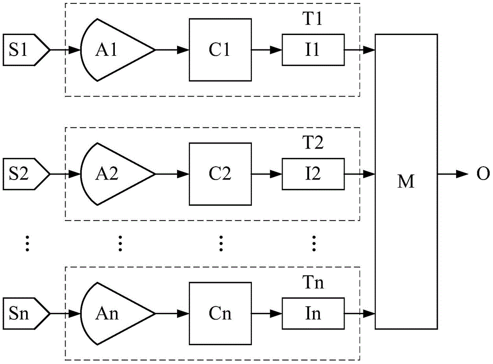
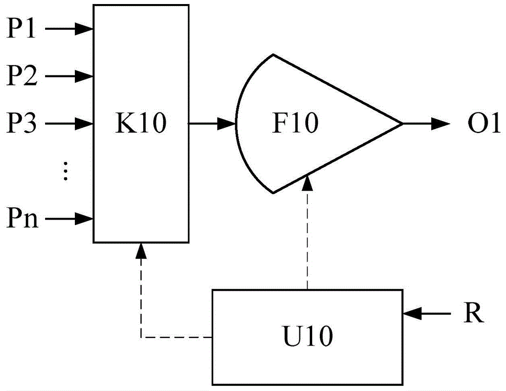
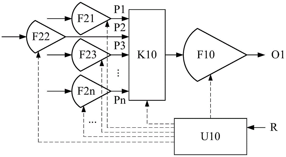
[0050] The following will combine Figure 2 to Figure 13 Describe this application in detail, wherein the same reference numerals represent the same or similar equipment or signals, the solid lines and their arrows represent the transmission direction of signals or data and the coupling or control relationship between related components, and the dotted lines and their arrows only represent A control relationship, an ellipsis indicates that multiple similar structures or compon...
PUM
 Abstract
Description
Claims
Application Information