LC filtering system, LC filtering circuit, electronic circuit and device

A filter circuit and capacitor technology, applied in the field of electricity, can solve the problems that signal filtering cannot be used, high-voltage circuit filtering cannot be used, etc.

Active Publication Date: 2015-12-09
徐州大安玻璃有限公司
View PDF2 Cites 2 Cited by
  • Summary
  • Abstract
  • Description
  • Claims
  • Application Information

AI Technical Summary

Problems solved by technology

[0002] The programmable filters with real-time adjustability in the prior art can only be used for signal filtering and cannot be used for high-power circuit filtering or high-voltage circuit filtering. It is worth improving

Method used


Image

  • LC filtering system, LC filtering circuit, electronic circuit and device
  • LC filtering system, LC filtering circuit, electronic circuit and device
  • LC filtering system, LC filtering circuit, electronic circuit and device

Examples


Embodiment 1

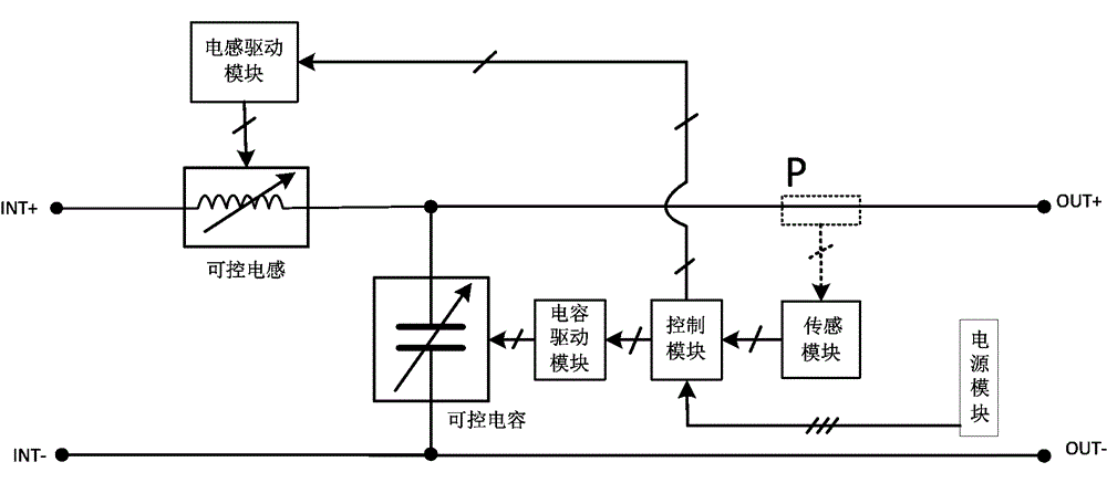
[0068] Implementation example 1, such as figure 1 As shown, the LC filter system is characterized in that it includes a first input node INT+, a second input node INT-, a first output node INT+, a second output node INT-, a capacitor drive module, a controllable capacitor, an inductance drive module, Controllable inductance, control module, sensing module, sampling point P, power module;

[0069] One functional terminal of the controllable inductor is connected to the first input node INT+, and the other functional terminal of the controllable inductor is electrically connected to the first output node OUT+;

[0070] There is an electrical connection between one functional terminal of the controllable capacitor and the first output terminal OUT+, and an electrical connection between the other functional terminal of the controllable capacitor and the second output terminal OUT-;

[0071] There is an electrical connection for transmitting electric energy between the power suppl...

Embodiment 2

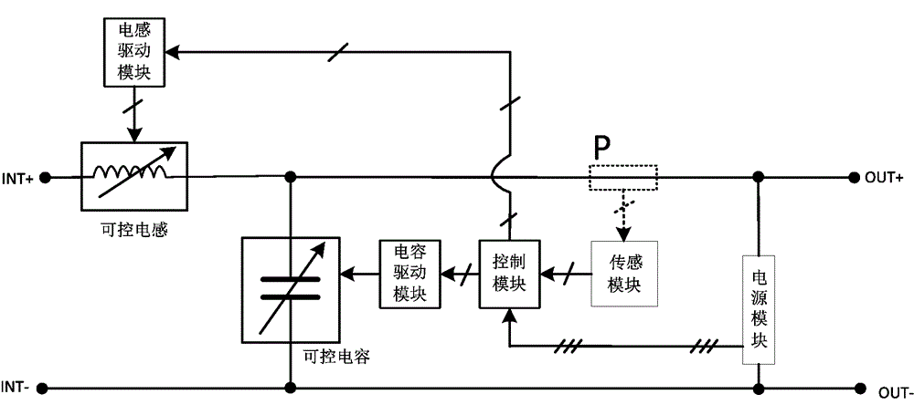
[0076] Implementation example 2, such as figure 2 As shown, based on the LC filter system described in Example 1, it is characterized in that: one input terminal of the power module is connected to the first output node OUT+ and the connection point is located on the electrical path between the sampling point P and the first output node OUT+ , the other input end of the power module is connected to the second output node OUT-.

Embodiment 3

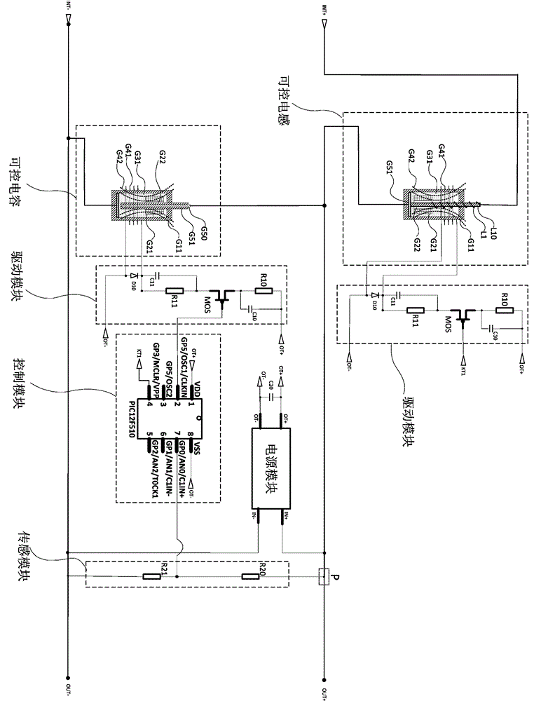
[0077] Implementation example 3, such as image 3 As shown, an LC filter circuit is characterized in that it includes a first input node INT+, a second input node INT-, a first output node INT+, a second output node INT-, a capacitor drive module, a controllable capacitor, and an inductance drive Module, controllable inductor, control module, sensor module, sampling point P, power module;

[0078] The characteristics of the controllable capacitor are as follows: including insulating container G11, conductive liquid G31, floating body G21, bottom electrode G51, capacitor rod G50, insulating layer G51, electromagnetic coil G41,

[0079] The insulating container G11 has a stable shape. The shape of the insulating container G11 is cylindrical. The container of the insulating container G11 is cylindrical. The cavity of the insulating container G11 is not easy to change in shape.

[0080] The conductive liquid G31 is contained in the cavity of the insulating container G11, the volu...


PUM


Abstract

The invention provides an LC filtering system. The LC filtering system is characterized by comprising a first input node (INT+), a second input node (INT-), a first output node (INT+), a second output node (INT-), a capacitor driving module, a controllable capacitor, an inductor driving module, a controllable inductor, a control module, a sensing module, a sampling point (P) and a power module. An LC filter circuit is based on the concretization of the LC band-pass filtering system. An electronic circuit is provided with the LC filtering circuit. A device is provided with the LC filtering circuit. The LC filtering system is long in service life, low in manufacturing cost and good in isolation, and can be applied to high-power weak electricity power supply circuits, power circuits and ultrahigh-voltage power circuits.

Description

technical field [0001] The invention belongs to the field of electricity, and in particular relates to an LC filter system, an LC filter circuit, an electronic circuit and equipment. Background technique [0002] The programmable filters with real-time adjustability in the prior art can only be used for signal filtering and cannot be used for high-power circuit filtering or high-voltage circuit filtering, so it is worth improving. Contents of the invention [0003] In order to solve the problems described in the technical background, the present invention proposes an LC filter system, an LC filter circuit, an electronic circuit, and equipment. [0004] The present invention has the following technical contents. [0005] 1. LC filter system, characterized in that it includes a first input node (INT+), a second input node (INT-), a first output node (INT+), a second output node (INT-), a capacitor drive module, and Capacitor control, inductance drive module, controllable...

Claims


Application Information

Patent Timeline
IPC IPC(8): H03H11/00
Inventor 林谷
Owner 徐州大安玻璃有限公司
Why Eureka
Try Eureka