Hand-eye calibration method employing two-dimension laser vision sensor and robot

A visual sensor, two-dimensional laser technology, applied in instruments, measuring devices, etc., can solve problems such as poor practicability and performance interference

Active Publication Date: 2015-12-16
SOUTH CHINA UNIV OF TECH
View PDF8 Cites 42 Cited by
  • Summary
  • Abstract
  • Description
  • Claims
  • Application Information

AI Technical Summary

Problems solved by technology

In some special industrial environments, such as strong arc light, dust, smoke and other adverse interference factors in the welding site, the performance of traditional CCD cameras has been seriously disturbed, and traditional CCD cameras cannot perform well in this environment. to complete the task, poor practicality

Method used


Image

  • Hand-eye calibration method employing two-dimension laser vision sensor and robot
  • Hand-eye calibration method employing two-dimension laser vision sensor and robot
  • Hand-eye calibration method employing two-dimension laser vision sensor and robot

Examples


Embodiment

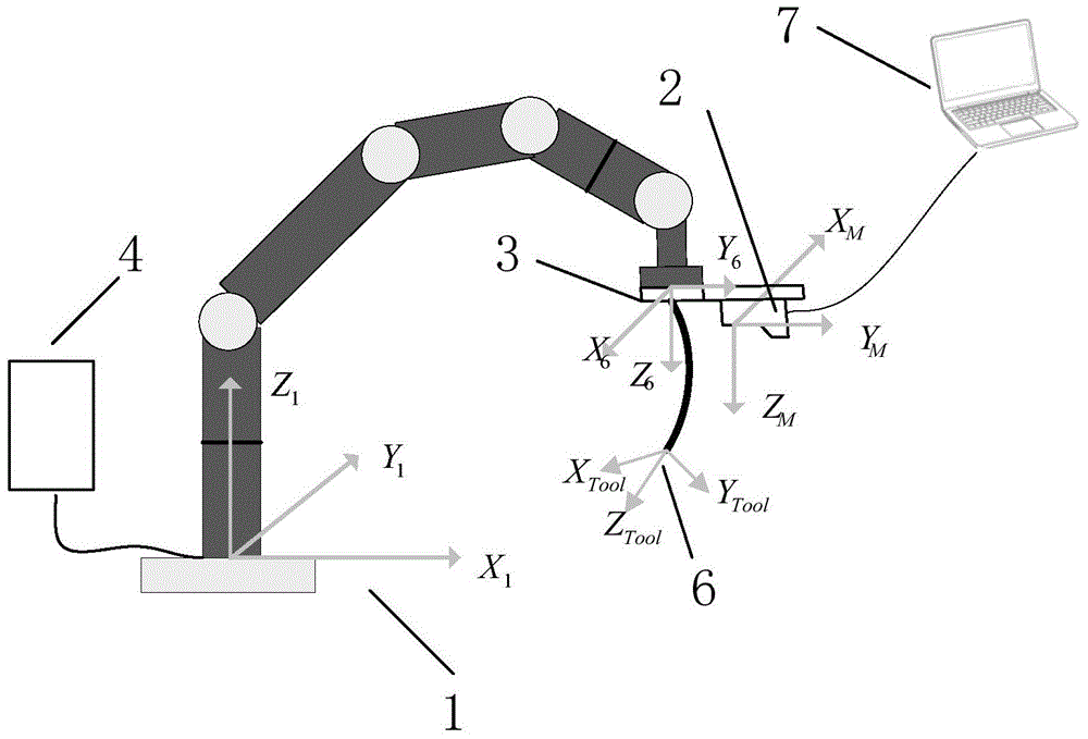
[0093] A two-dimensional laser sensor is installed on the end flange of the robot (including robot controller and teaching box) through the mounting bracket. The sensor communicates with the computer, and the computer receives the measurement data returned by the sensor.

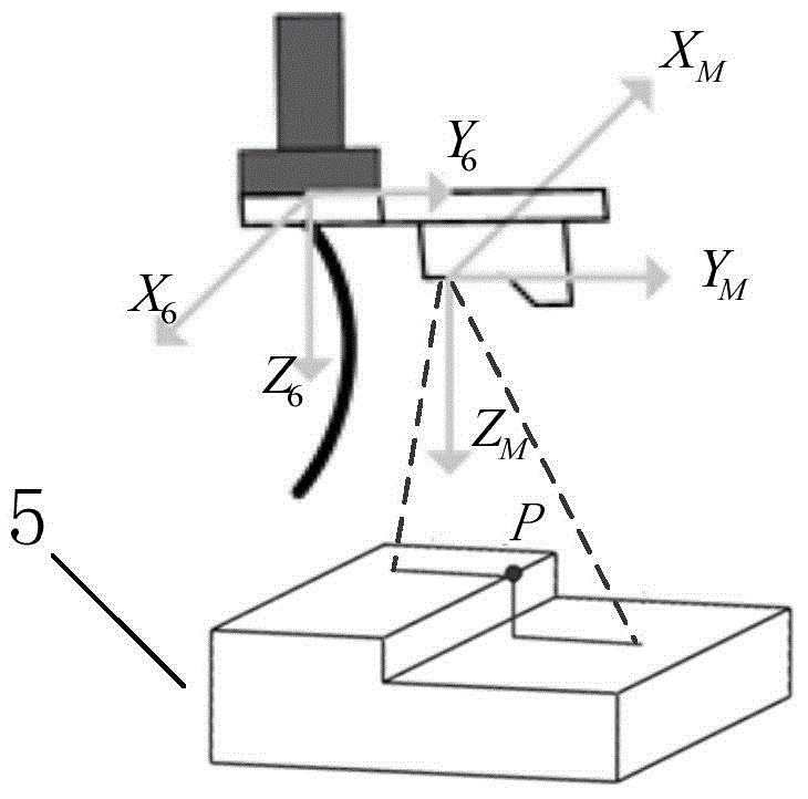
[0094] When the laser beam emitted by the two-dimensional laser sensor is projected onto the surface of the measured object, the laser beam will form an image consistent with the surface contour of the measured object. There are a series of continuous and uniformly distributed P laser sampling points on the laser beam. Then the sensor returns the Z-axis and X-axis coordinate values ​​of the P sampling points in the laser beam relative to the sensor measurement coordinate system.

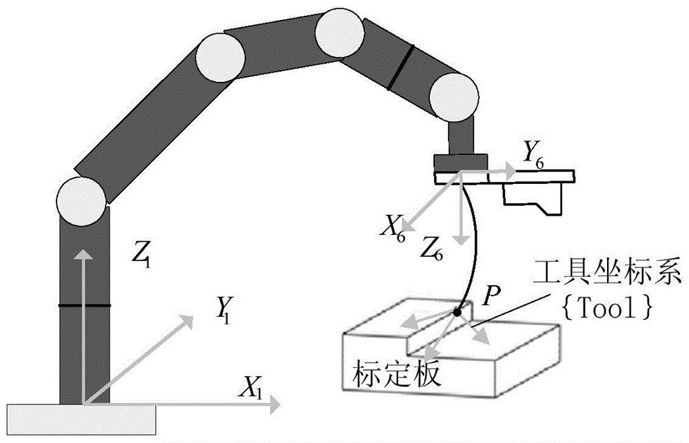
[0095] Combined with the calibration board, laser sensors and robots are used to obtain the data required for hand-eye calibration. The method also uses a computer to obtain the measurement data of the two-dimensional laser sensor,...


PUM


Abstract

A disclosed hand-eye calibration method employing a two-dimension laser vision sensor and a robot comprises the following steps: step A, establishing a mathematic module of a calibration algorithm; step B, making enforcement operation step for hand-eye calibration. The step of establishing the mathematic module of the calibration algorithm realizes derivation of the mathematic module of the calibration algorithm; and the step of making the enforcement operation step for hand-eye calibration solves the concrete enforcement operation flow in the h and-eye calibration process by employing the two-dimension laser vision sensor and the robot. The method possesses the advantages of being simple, practical, agile, good in precision and the like.

Description

technical field [0001] The present invention relates to a hand-eye calibration technology for laser sensors and robots, in particular to a two-dimensional laser vision sensor and a hand-eye calibration method for robots. And the two-dimensional laser sensor is the measuring device. The attitude change of the robot drives the laser sensor to measure several fixed points in space, and records the attitude of the robot and the coordinate values ​​of the space point in the robot base coordinate system and the laser sensor measurement coordinate system respectively. The algorithm solves the transformation relationship between the sensor measurement coordinate system and the robot end flange coordinate system, that is, the hand-eye calibration of the two-dimensional laser sensor. Background technique [0002] Because the vision system has good detection performance and positioning performance, the development of robot vision system has become a hot spot and focus in the field of r...

Claims


Application Information

Patent Timeline
Patent Type & Authority Applications(China)
IPC IPC(8): G01C25/00
Inventor 张铁李波邹焱飚
Owner SOUTH CHINA UNIV OF TECH
Why Eureka
Try Eureka