Al technical title is built by PatSnap Al team. It summarizes the technical point description of the patent document.
A tunnel and railway technology, which is applied in the field of road safety supporting facilities, can solve the problems of non-waterproof heating elements, affecting the opening of tunnels, affecting heat transfer, etc., and achieves the effects of high electrothermal conversion efficiency, long service life and easy maintenance
Inactive Publication Date: 2017-03-22
WUHAN UNIV
View PDF7 Cites 0 Cited by
Summary
Abstract
Description
Claims
Application Information
AI Technical Summary
This helps you quickly interpret patents by identifying the three key elements:
Problems solved by technology
Method used
Benefits of technology
Problems solved by technology
However, in this technical solution, a roof is provided between the heating element and the top wall of the tunnel. The existence of the roof will affect the transfer of heat from the heating element to the tunnel roof; and this solution does not treat the water flowing down from the top of the tunnel. In winter, when the temperature is relatively low, the water will freeze into ice. As the amount of ice increases, it may affect the smooth flow of water and even affect the opening of the tunnel.
The heating element used in this patent is not waterproof, and it will be dangerous when water from the roof of the tunnel seeps into the interior of the housing
Method used
Image
Click on the blue label to locate the original text in one second.
Reading with bidirectional positioning of images and text.
Examples
Embodiment Construction
[0023] In order to facilitate those of ordinary skill in the art to understand and implement the present invention, the present invention will be described in further detail below in conjunction with the accompanying drawings and embodiments. It should be understood that the implementation examples described here are only used to illustrate and explain the present invention, and are not intended to limit this invention.
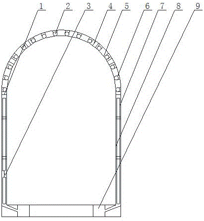
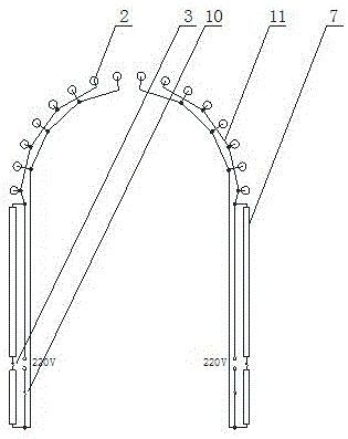
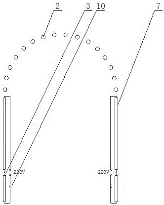
[0024] please see figure 1 , figure 2 , image 3 , Figure 4 and Figure 5 , a railway tunnel deicing device provided by the present invention comprises an ice-melting cornice 1, a first ceramic electric heating tube 2, a first temperature control switch 3, a support frame 4, an aluminum alloy cover plate 5, a fixing card 6, a second Ceramic electric heating tube 7, aluminum alloy downpipe 8, drainage blind ditch 9, switch 10, wire 11, enamel layer 12, ceramic layer 13, electric heating wire 14, cornice longitudinal slope 15, U-shaped casing, second temp...
PUM
Abstract
The invention discloses a railway tunnel deicing device. The railway tunnel deicing device comprises an ice melting cornice, a first ceramic electric heating pipe, a first temperature control switch, a support frame, an aluminum alloy cover plate, a fastening clamp, a second ceramic electric heating pipe, an aluminum alloy downpipe, a draining blind ditch, a switch, a wire, a ceramic glaze layer, a ceramic layer, electric heating wires, a cornice longitudinal slope, a U-shaped sleeve and a second temperature control switch. The temperature at the top of a tunnel can be kept between 10DEG C and 30DEG C, so that water leaking from the top of the tunnel cannot ice but directly drop on the cover plate at the lower part. Then, water flows into the downpipe along the ice melting cornice. Finally, water flows into the underground draining blind ditch. The ceramic electric heating pipes, formed by using ceramic as a base body and winding the electric heating wires in series, are high in electric heating conversion efficiency, rapidly rise the temperature, are low in thermal inertia, resistant to high temperature, resistant to corrosion, great in thermalchemical performance stability, long in service life, high in insulating strength and free of pollution, and can save energy by 30% more or less in comparison with other electric heating elements. The production of ice streams can be radically prevented.
Description
technical field [0001] The invention belongs to the technical field of road safety supporting facilities, and relates to a deicing device, in particular to a railway tunnel deicing device. Background technique [0002] Because the top of the railway tunnel is prone to leakage and dripping, many ice hangs are often formed on the top wall of the tunnel in winter. Especially in winter, as the train enters the tunnel, a large amount of cold air flows into the tunnel instantly as the train travels. Wall hanging ice badly. If the ice hanging touches the catenary wire suspended on the top of the tunnel, the catenary wire will be burned due to the short circuit of the circuit, which will bring great danger to the railway transportation. The method that mainly adopts at present is artificial deicing, promptly removes ice hanging with the method for manual beating. But this deicing method is costly and dangerous, and does not solve this problem well. [0003] Another method is to i...
Claims
Application Information
Patent Timeline
Application Date:The date an application was filed.
Publication Date:The date a patent or application was officially published.
First Publication Date:The earliest publication date of a patent with the same application number.
Issue Date:Publication date of the patent grant document.
PCT Entry Date:The Entry date of PCT National Phase.
Estimated Expiry Date:The statutory expiry date of a patent right according to the Patent Law, and it is the longest term of protection that the patent right can achieve without the termination of the patent right due to other reasons(Term extension factor has been taken into account ).
Invalid Date:Actual expiry date is based on effective date or publication date of legal transaction data of invalid patent.