Automatic bee keeping device

An automatic, honeycomb technology, applied in the field of bee farming, can solve the problems of hard life and labor-intensive

Active Publication Date: 2016-05-04
KUNMING UNIV OF SCI & TECH
View PDF6 Cites 13 Cited by
  • Summary
  • Abstract
  • Description
  • Claims
  • Application Information

AI Technical Summary

Problems solved by technology

During the honey collection period, it is necessary to take out the collected honey comb in the sealed box every day, which is a labor-intensive work in itself.
In additi

Method used


Image

  • Automatic bee keeping device
  • Automatic bee keeping device
  • Automatic bee keeping device

Examples


Embodiment 1

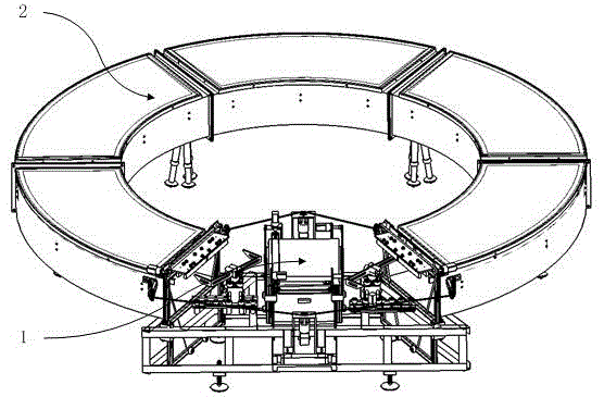
[0066] Embodiment 1: as Figure 1-24 As shown, an automatic beekeeping device, including an automatic spleen-removing honeycomb 1, and a honeycomb storage box 2;

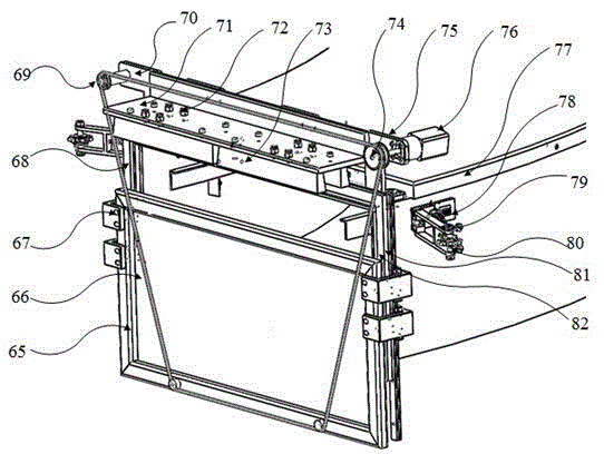
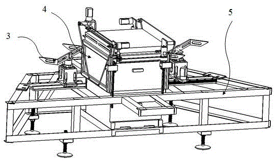
[0067] The automatic spleen transfer honeycomb 1 includes a honeycomb transfer manipulator 3, a honeycomb 4, and a support 5;

[0068] The honeycomb transfer manipulator 3 includes a gear 6, a rack 7, a horizontal moving motor 8, a support fork 9, a bearing support 10, a support fork motor 11, a support fork motor support 12, a slider 13, a horizontal guide rail 14, and a manipulator base 15; wherein the gear 6 and the rack 7 are meshed, the rack 7 is installed on the manipulator base 15, the output shaft of the horizontal movement motor 8 is connected with the gear 6, the horizontal movement motor 8 is installed on the slider 13, and the support fork 9 is installed on the bearing On the support 10, the supporting fork 9 is connected with the output shaft of the supporting fork motor 11, the supporting fork motor 1...

Embodiment 2

[0090] Embodiment 2: as Figure 1-24 As shown, an automatic beekeeping device, including an automatic spleen-removing honeycomb 1, and a honeycomb storage box 2;

[0091] The automatic spleen transfer honeycomb 1 includes a honeycomb transfer manipulator 3, a honeycomb 4, and a support 5;

[0092] The honeycomb transfer manipulator 3 includes a gear 6, a rack 7, a horizontal moving motor 8, a support fork 9, a bearing support 10, a support fork motor 11, a support fork motor support 12, a slider 13, a horizontal guide rail 14, and a manipulator base 15; wherein the gear 6 and the rack 7 are meshed, the rack 7 is installed on the manipulator base 15, the output shaft of the horizontal movement motor 8 is connected with the gear 6, the horizontal movement motor 8 is installed on the slider 13, and the support fork 9 is installed on the bearing On the support 10, the supporting fork 9 is connected with the output shaft of the supporting fork motor 11, the supporting fork motor 1...

Embodiment 3

[0108] Embodiment 3: as Figure 1-24 As shown, an automatic beekeeping device, including an automatic spleen-removing honeycomb 1, and a honeycomb storage box 2;

[0109] The automatic spleen transfer honeycomb 1 includes a honeycomb transfer manipulator 3, a honeycomb 4, and a support 5;

[0110] The honeycomb transfer manipulator 3 includes a gear 6, a rack 7, a horizontal moving motor 8, a support fork 9, a bearing support 10, a support fork motor 11, a support fork motor support 12, a slider 13, a horizontal guide rail 14, and a manipulator base 15; wherein the gear 6 and the rack 7 are meshed, the rack 7 is installed on the manipulator base 15, the output shaft of the horizontal movement motor 8 is connected with the gear 6, the horizontal movement motor 8 is installed on the slider 13, and the support fork 9 is installed on the bearing On the support 10, the supporting fork 9 is connected with the output shaft of the supporting fork motor 11, the supporting fork motor 1...


PUM


Abstract

The invention relates to an automatic bee keeping device and belongs to the technical field of bee keeping. The automatic bee keeping device comprises an automatic comb moving hive and hive comb storage bins. The automatic comb moving hive comprises comb transfer manipulators, a comb and a support. The hive comb storage bins comprise interface boxes, relay boxes and main transmission devices. By means of the automatic bee keeping device, automatic placing-in of empty combs and automatic taking-out of combs filled with gathered honey are achieved; the combs are taken and placed automatically, so that the interval between comb taking and placing is greatly prolonged, great help is offered to the improvement in automatic level of bee houses, the bee keeping productivity can be greatly improved, labor cost is saved, production efficiency is improved, and foundation is laid to full-automatic bee keeping.

Description

technical field [0001] The invention relates to an automatic beekeeping device, which belongs to the technical field of bee breeding. Background technique [0002] At present, bee breeding relies heavily on manpower to extract the honeycomb from the beehive, and then put the honey into a manual honey shaker or an electric honey shaker, and use centrifugal force to shake out the honey. During the honey collection period, the honey comb that has been collected in the sealed box will be taken out every day, which is a labor-intensive work in itself. In addition, many farms are built in the mountains and forests at present, and people need to be stationed in the mountains and forests for a long time. The work and life are very hard. In order to improve the production efficiency during the honey collection period, the present invention proposes a method that can remove the honeycomb that has already been collected from the honeycomb relay box, and use the honeycomb transfer mani...

Claims


Application Information

Patent Timeline
IPC IPC(8): A01K47/00A01K47/02A01K47/06A01K59/00A01K59/02
CPCA01K47/00A01K47/02A01K47/06A01K59/00A01K59/02
Inventor 蒋红海袁锐波张天驿罗璟钱俊兵何祖顺杨晓京
Owner KUNMING UNIV OF SCI & TECH
Why Eureka
Try Eureka