Assembly structure of bottom cover plate of terminal equipment and its use method

A terminal equipment and assembly structure technology, which is applied in the field of terminal equipment bottom cover assembly structure, can solve the problems of unsightly appearance, poor connection strength, large gap, etc., and achieve the effects of convenient operation, long service life and reliable installation

Active Publication Date: 2018-07-06
HUNAN GREATWALL INFORMATION FINANCIAL EQUIP
View PDF5 Cites 0 Cited by
  • Summary
  • Abstract
  • Description
  • Claims
  • Application Information

AI Technical Summary

Problems solved by technology

After assembly, the gap between the bottom cover and the bottom cover is relatively large, which is not beautiful after assembly
The second assembly method has a problem with the assembly structure of the battery cover: insert the pin at the front end of the cover into the groove of the lower cover, rotate the bottom cover and assemble it on the lower cover, and lock the rear of the cover with two screws, and the wires in it The cable must be fixed on the cover. When the cable is fixed on the lower cover, when the cover is turned over, the L-shaped notch of the cover will interfere with the fixing groove of the cable. When the cable is fixed through the cover, the connection strength is slightly weaker. In addition, when the cover is completely removed, the cable must be separated from the socket of the cover
The above two battery cover assembly methods have certain limitations when applied to this device.

Method used


Image

  • Assembly structure of bottom cover plate of terminal equipment and its use method
  • Assembly structure of bottom cover plate of terminal equipment and its use method
  • Assembly structure of bottom cover plate of terminal equipment and its use method

Examples


Embodiment Construction

[0032] The present invention will be further described below in conjunction with accompanying drawing.

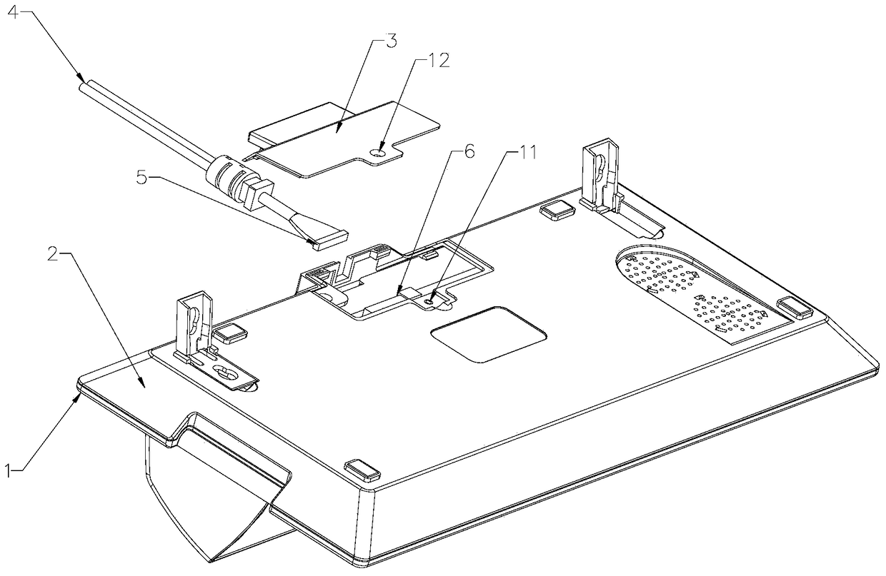
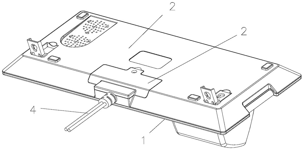
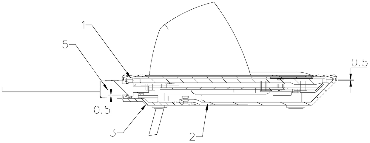
[0033] see figure 1 , figure 2 , image 3 , Figure 4 with Figure 5 , The upper cover 1 of the interactive terminal and the lower cover 2 of the interactive terminal are fixed with buckles and then tightened with screws. The cable 4 is fixed on the outside of the bank counter, and the connector 5 of the cable 4 is inserted into the socket 6 of the main board, and the socket 6 of the main board is arranged on the inner side of the lower cover 2 of the interactive terminal. The outer side of the interactive terminal lower cover 2 is provided with a lower cover rib position 10, the interactive terminal lower cover 2 is provided with an interactive terminal lower cover button position 9 near the outer side, and the inner side of the interactive terminal lower cover 2 away from the lower cover rib position 10 is provided with There is a first screw hole 11, the rear end o...


PUM


Abstract

The invention discloses a terminal equipment type bottom cover plate assembling structure and an application method thereof; a lower cover rib position (10) is arranged outside an interactive terminal lower cover (2); a position, close to the outer side, of the interactive terminal lower cover (2) is provided with an interactive terminal lower cover buckle position (9); the inner side, far away from the lower cover rib position (10), of the interactive terminal lower cover (2) is provided with a first screw hole (11); the rear end of the a bottom cover plate (3) is provided with an outer rib position (8); a position, close to the rear end, of the bottom cover plate (3) is provided with a bottom cover hook (7); the front end of the bottom cover plate (3) is provided with a screw through hole (12); in assembling, the outer rib position (8) and the lower cover rib position (10) are jointed, the bottom cover hook (7) is buckled on the interactive terminal lower cover buckle position (9), and the screw through hole (12) and the first screw hole (11) are connected through a screw or an elastic buckle. The terminal equipment type bottom cover plate assembling structure is stable in fixation, long in life, reliable in mounting, and the application method thereof is provided.

Description

technical field [0001] The present invention relates to a cover plate assembly structure, in particular to a terminal equipment type bottom cover plate assembly structure, and also relates to a method for using the terminal equipment type bottom cover plate assembly structure. Background technique [0002] In banking terminal equipment, due to the needs of use, it is often necessary to remove the rear cover for firmware upgrades and cable removal and maintenance operations. [0003] A commonly used battery cover assembly method is to make a latch at the propelling part. After the assembly is in place, lock the screw or buckle at the rear of the battery cover to fix it; another battery cover assembly method is to make a front latch at the root of the cover. Insert, use the battery cover to rotate, and fix it with the elastic cantilever at the rear of the battery cover or screws. When removing, press the elastic cantilever of the battery cover to make the buckle of the elastic...

Claims


Application Information

Patent Timeline
Patent Type & Authority Patents(China)
IPC IPC(8): G07F9/10
CPCG07F9/10
Inventor 李洪雷刘永红王赛
Owner HUNAN GREATWALL INFORMATION FINANCIAL EQUIP
Why Eureka
Try Eureka