A lighting energy-saving bypass device

A bypass device and bypass technology, applied in the electrical field, can solve the problems of large size and high cost of the switching device, and achieve the effects of small size, low cost and small control current

Active Publication Date: 2018-06-01
JINGJIANG YONGSHENG OPTOELECTRONICS TECH
View PDF8 Cites 0 Cited by
  • Summary
  • Abstract
  • Description
  • Claims
  • Application Information

AI Technical Summary

Problems solved by technology

[0002] In some commonly used power bypass devices, two sets of AC non-contact switches or multiple contactors are usually used to switch between two power outputs. In this bypass mode, the current passing through the bypass device is the electrical main All the current in the loop, so the switching device is bulky and expensive

Method used


Image

  • A lighting energy-saving bypass device
  • A lighting energy-saving bypass device

Examples


Embodiment Construction

[0017] Embodiments of the present invention will be described in detail below in conjunction with the accompanying drawings.

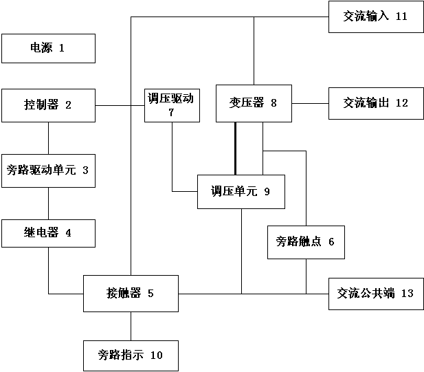
[0018] Please see figure 1 , a lighting energy-saving bypass device, including: power supply [1], controller [2], bypass drive unit [3], relay [4], contactor [5], bypass contact [6], regulator voltage driver[7], transformer[8], voltage regulating unit[9], bypass indication[10], AC input[11], AC output[12], AC common terminal[13]; controller[2] and The bypass drive unit [3] and voltage regulation drive [7] form an electrical connection; contactor [5] and relay [4], bypass contact [6], voltage regulation unit [9], bypass indication [10] , AC input [11], AC common terminal [13] constitute electrical connection; transformer [8] and bypass contact [6], voltage regulating unit [9], AC input [11], AC output [12] constitute electrical connection connection; the voltage regulation unit [9] forms an electrical connection with the contactor [5], the bypass cont...


PUM


Abstract

The invention discloses an energy-saving bypass device for illumination. The energy-saving bypass device comprises a power supply [1], a controller [2], a bypass drive unit [3], a relay [4], a contactor [5], a bypass contact [6], a voltage regulating drive [7], a transformer [8], a voltage regulating unit [9], a bypass indication [10], an AC input [11], an AC output [12] and an AC common port [13], wherein the contactor [5] is electrically connected with the relay [4], the bypass contact [6], the voltage regulating unit [9], the bypass indication [10], the AC input [11] and the AC common port [13]; and the transformer [8] is electrically connected with the bypass contact [6], the voltage regulating unit [9], the AC input [11] and the AC output [12]. Bypass control is carried out on a high-voltage side of the transformer, so that the control current is relatively low; and required electric elements are small in size and low in cost.

Description

technical field [0001] The invention relates to a power supply bypass device, in particular to a lighting energy-saving bypass device for primary voltage regulation of a transformer, and belongs to the electrical technical field. Background technique [0002] In some commonly used power bypass devices, two sets of AC non-contact switches or multiple contactors are usually used to switch between two power outputs. In this bypass mode, the current passing through the bypass device is the electrical main All the current in the loop, so the switching device is bulky and expensive. [0003] At present, there are also some other devices that realize dual power supply switching or bypassing, such as patents CN201110131174.8, CN201110121548.8, CN201110051324.4, CN200710133614.7, which can realize switching between normal power supply and backup power supply, and each has its own advantages , but the current passing through these switching devices is also the entire current in the e...

Claims


Application Information

Patent Timeline
Patent Type & Authority Patents(China)
IPC IPC(8): H05B37/02
CPCH05B47/10Y02B20/40
Inventor 涂金龙韩京海郭新兰王晓丽
Owner JINGJIANG YONGSHENG OPTOELECTRONICS TECH
Why Eureka
Try Eureka