Level shift circuit

A level shift circuit and level shift technology, which are applied in logic circuit interface devices, eliminate voltage/current interference, logic circuit connection/interface layout, etc., can solve the problems of high process requirements and high cost, reduce manufacturing costs, The effect of reducing the requirements of the production process and the simple structure

Active Publication Date: 2016-06-01
SILLUMIN SEMICON CO LTD
View PDF6 Cites 6 Cited by
  • Summary
  • Abstract
  • Description
  • Claims
  • Application Information

AI Technical Summary

Problems solved by technology

In the prior art, Zener tubes are usually used as clamping components in level shift circuits. This structure has the problems of high cost and high process requirements.

Method used


Image

  • Level shift circuit
  • Level shift circuit
  • Level shift circuit

Examples


Embodiment Construction

[0038] The present invention will be described in detail below in terms of specific embodiments in conjunction with the accompanying drawings. The following examples will help those skilled in the art to further understand the present invention, but do not limit the present invention in any form. It is to be noted that other embodiments may be utilized or structural and functional modifications may be made to the embodiments set forth herein without departing from the scope and spirit of the invention.

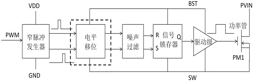
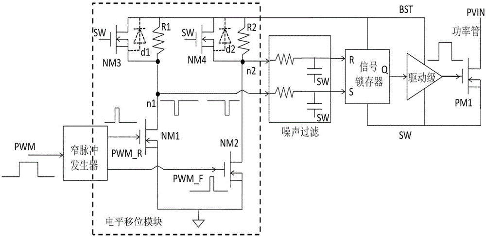
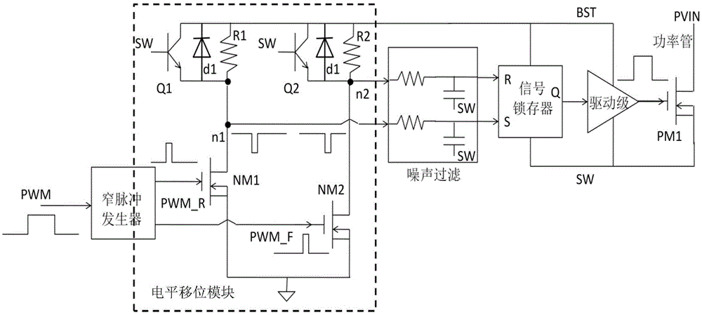
[0039] A level shift circuit provided in the present invention is used to control the on-off of the power tube, such as figure 1 As shown in the structural block diagram, it includes: a narrow pulse generator, a level shift module, a signal latch, and a driver stage circuit;

[0040] The narrow pulse generator is used to output the first narrow pulse signal according to the rising edge of the low-voltage duty ratio signal, and output the second narrow pulse signal according t...


PUM


Abstract

The invention provides a level shift circuit for controlling on-off of a power tube. The level shift circuit comprises a narrow pulse generator which outputs a first narrow pulse signals according to a rising edge of low-pressure duty ratio signals and outputting second narrow pulse signals according to a falling edge of the input low-pressure duty ratio signals; a level shift module which reverses the first narrow pulse signals and lifts level to somewhere between the positive electrode of a floating power supply and the ground to obtain first high-level reverse signals and reverses the second narrow pulse signals and lifts level to somewhere between the positive electrode of the floating power supply and the ground to obtain second high-level reverse signals; a signal latch register which outputs high-pressure duty ratio signals according to the first high-level reverse signals and the second high-level reverse signals; and a driving-grade circuit which controls the opening and closing of the power tube according to the high-pressure duty ratio signals and has an input end accessed to the high-level duty ratio signals and an output end connected with the grid of the power tube. According to the invention, the short-pulse driving capability is large, level shift is rapidly realized, the level shift time is shortened, and power consumption is reduced.

Description

technical field [0001] The invention relates to the technical field of control of high-voltage devices, in particular to a level shift circuit suitable for floating power supply rails. Background technique [0002] The level shift circuit converts the low-voltage control signal into a high-voltage control signal, and realizes the control of the low-voltage logic on the high-voltage power output stage. ) and FLASH memory circuits have been widely used. In the field of control technology for high-voltage devices, the control circuit and high-voltage output drive circuit can be integrated to achieve high withstand voltage, high current, and high precision. [0003] A conventional level shift circuit converts a low-voltage control signal into a high-voltage control signal for driving an output-stage NMOS (should be an NMOS) tube operating under high voltage. As a key circuit connecting the control circuit and the output driver stage, the level shift circuit requires fast respo...

Claims


Application Information

Patent Timeline
Patent Type & Authority Applications(China)
IPC IPC(8): H03K19/0175H03K19/003
CPCH03K19/00346H03K19/017509
Inventor 吴国明
Owner SILLUMIN SEMICON CO LTD
Why Eureka
Try Eureka