Clamp for assembling and expanding conducting bar of motor rotor

A technology for tightening fixtures and motor rotors, which is applied in the manufacture of stator/rotor bodies, etc., can solve the problems of unfixed guide bars at both ends, not tight guide bars, and unsafety, so as to improve positioning accuracy and expansion effects. The effect of reducing labor intensity and occupying a small area

Inactive Publication Date: 2016-06-08
襄阳中车电机技术有限公司
View PDF0 Cites 4 Cited by
  • Summary
  • Abstract
  • Description
  • Claims
  • Application Information

AI Technical Summary

Problems solved by technology

[0002] At present, there are the following disadvantages in the process of assembling and tightening the copper bar rotor guide bar of the motor known or being used by the motor factory: ① Mark the line to determine the length of the guide bar protruding from both ends of the rotor core. Observe the insertion position of the guide bar. The operation is cumbersome, the positioning of the guide bar is not accurate, and the lengths of the two ends of the protruding iron core are different; The iron core slides out of the groove, and the two ends of the guide bar need to be tightened by hand when it is inflated. The operation is cumbersome and unsafe, and the guide bar does not expand tightly.

Method used


Image

  • Clamp for assembling and expanding conducting bar of motor rotor

Examples


Embodiment Construction

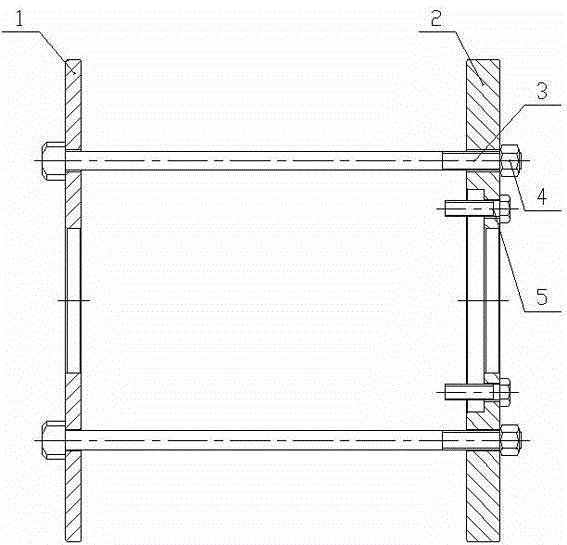
[0009] Such as figure 1 As shown, the present invention comprises a driving end pressing plate 1 and a non-driving end pressing plate 2, the driving end pressing plate 1 and the non-driving end pressing plate 2 are all circular steel plates, and four The screw rod 3 is connected and fixed with the nut 4; the four circular holes connecting the screw rod 3 on the drive end pressure plate 1 correspond to the four ventilation holes on the rotor core; the outer circle size of the non-drive end pressure plate 2 is smaller than the rotor core The outer diameter size and the inner circle size are larger than the diameter of the rotor core gear shaft. There is an annular step on the inner ring of the non-drive end pressure plate 2, and the annular step is set on the side of the transmission end pressure plate 1. There are four bolts 5 evenly connected along the circumference on the annular step; working principle: when the present invention is in use, the nut 4 on the four screw rods 3...


PUM


Abstract

The invention relates to a clamp for assembling and expanding a conducting bar of a motor rotor, especially to a clamp for assembling and expanding the conducting bar of the copper bar rotor of a motor, and aims at solving the problems that the length of the rotor bar stretching out of two ends of a rotor core is determined through marking lines when a present electric machine copper rotor bar is assembled and expanded, operation is complex, the rotor bar cannot be accurately positioned, lengths, stretching out of two ends of a rotor core, of the rotor bar are different, two ends of the rotor bar are not fixed when the rotor bar is expanded, and the rotor bar is easy to slip off a rotor core groove when the expanding force is over large or the direction is inclined. A circular-ring-shaped non-driving end pressure plate is connected to a driving end pressure plate through four screws, the inner circle of the non-driving end pressure plate is provided with a circular-ring-shaped stage, and four bolts are uniformly connected to the periphery of the ring stage. By adopting the clamp, the labor intensity is reduced, positioning precision of the rotor bar and the expanding effect are improved, the size is small, the weight is low, the floor space is small, and the clamp is suitable for assembling and expanding a batch of copper rotor bars at the same time.

Description

technical field [0001] The invention relates to special mechanical equipment in the motor manufacturing industry, in particular to a copper bar rotor guide bar assembly and expansion clamp for traction motors of subway vehicles. Background technique [0002] At present, there are the following disadvantages in the process of assembling and tightening the copper bar rotor guide bar of the motor known or being used by the motor factory: ① Mark the line to determine the length of the guide bar protruding from both ends of the rotor core. Observe the insertion position of the guide bar. The operation is cumbersome, the positioning of the guide bar is not accurate, and the lengths of the two ends of the protruding iron core are different; The iron core slides out of the groove, and the two ends of the guide bar need to be tightened by hand when expanding. The operation is cumbersome and unsafe, and the guide bar does not expand tightly. Contents of the invention [0003] The o...

Claims


Application Information

Patent Timeline
Patent Type & Authority Applications(China)
IPC IPC(8): H02K15/02
Inventor 龙振兴
Owner 襄阳中车电机技术有限公司
Why Eureka
Try Eureka