

Drill bit of cemented soil mixing pile drilling rig
A technology of cement-soil mixing piles and drill bits, which can be used in the direction of drill bits, earth square drilling, sheet pile walls, etc., and can solve problems such as inability to drill
Inactive Publication Date: 2016-07-06
青岛蓝天创先科技服务有限公司
View PDF5 Cites 0 Cited by
- Summary
- Abstract
- Description
- Claims
- Application Information
AI Technical Summary
Problems solved by technology
Method used
View moreImage
Smart ImageViewing Examples

Examples
Embodiment Construction
[0009] The summary of the invention has described the specific implementation of the present invention in detail, and will not repeat it. It needs to be explained as follows:
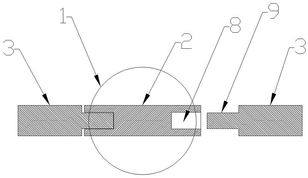
[0010] see Figure 4 , the drill tip (1) has tooth grooves, which can cut boulders; the groove (8) of the connecting arm (2) has a stop surface (10), when the blade (3) rotates upwards and touches the stop surface (10) , the blade (3) no longer rotates, and the blade (3) can be kept rotating at a certain inclination angle to squeeze small stones to the surrounding soil layer.
Login to View More PUM
 Abstract
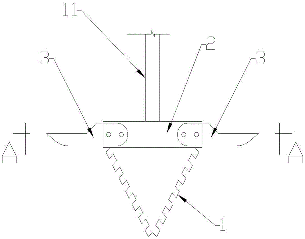
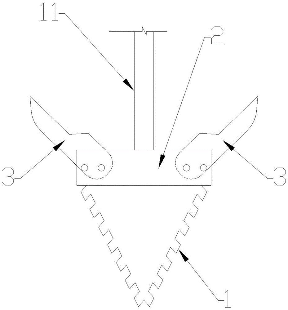
The invention provides a drill bit of a cemented soil mixing pile drilling rig, and the drill bit is mainly applied to the building construction field. The drill bit of the cemented soil mixing pile drilling rig is mainly composed of a drill point (1), a connecting arm (2), blades (3) and a drill rod (11). A construction method of the drill bit includes the steps that blade connecting plates (9) of the blades (3) are inserted into grooves (8) of the connecting arm (2), and holes A (4) and holes B (5) of the blades (3) are aligned with holes C (6) and holes D (7) of the connecting arm (2) correspondingly; one pin rod is inserted into the corresponding hole C (6) and the corresponding hole A (4), and another pin rod is inserted into the corresponding hole D (7) and the corresponding hole B (5); when the drill bit encounters a boulder and cannot conduct drilling, the pin rods in the holes C (6) and the holes A (4) are pulled out, then the drill bit is pressed down for drilling, and the two blades (3) are in an upward inclining state; the drill point (1) decomposes the boulder into small stone blocks through drilling and crushing when encountering the boulder, and the inclined blades (3) squeeze the small stone blocks to peripheral soil layers, so that the bolder in a pile hole is removed.
Description
technical field [0001] The invention is mainly used for the drill bit of a cement-soil mixing pile drilling rig in the field of building construction. Background technique [0002] The drill bits of the cement-soil mixing pile drilling rigs currently used in my country are all fixed blades, which can only be applied to common soil layers, and cannot be drilled into slightly larger boulders. Contents of the invention [0003] The present invention solves the above-mentioned problems, and it can crush and squeeze the boulder in the pile hole, so that the drill bit can drill normally. The present invention is mainly composed of a drill tip (1), a connecting arm (2), a blade (3), and a drill rod (11); the upper end of the connecting arm (2) is fixed to the lower end of the drill rod (11), and the connecting arm (2) The lower end of the drill point (1) is fixed to the upper end of the drill point (1), the left and right ends of the connecting arm (2) have holes C (6), holes D ...
Claims
Login to View More Application Information
Patent Timeline
 IPC IPC(8): E21B10/62E21B10/43E02D5/46
CPCE21B10/62E02D5/46E21B10/43
Inventor 薛峰彭宝安
Owner 青岛蓝天创先科技服务有限公司