Continuous Bill Sheet Cutting Machine

A cutting machine and bill technology, applied in metal processing, etc., can solve the problems such as rough tearing of bills, joint sheets, cutting difficulties, etc., and achieve the effect of smooth cutting edge, stable work and high work efficiency

Active Publication Date: 2017-06-06
HEBEI HUIJIN ELECTROMECHANICAL
View PDF9 Cites 0 Cited by
  • Summary
  • Abstract
  • Description
  • Claims
  • Application Information

AI Technical Summary

Problems solved by technology

[0004] The cutting machine currently on the market, when cutting bills of relatively hard paper, it is difficult to cut and often has a phenomenon of joint sheets. After cutting, the bills are not smooth at the torn part and have rough edges. This kind of cutting quality should be improved.

Method used


Image

  • Continuous Bill Sheet Cutting Machine
  • Continuous Bill Sheet Cutting Machine
  • Continuous Bill Sheet Cutting Machine

Examples


Embodiment 1

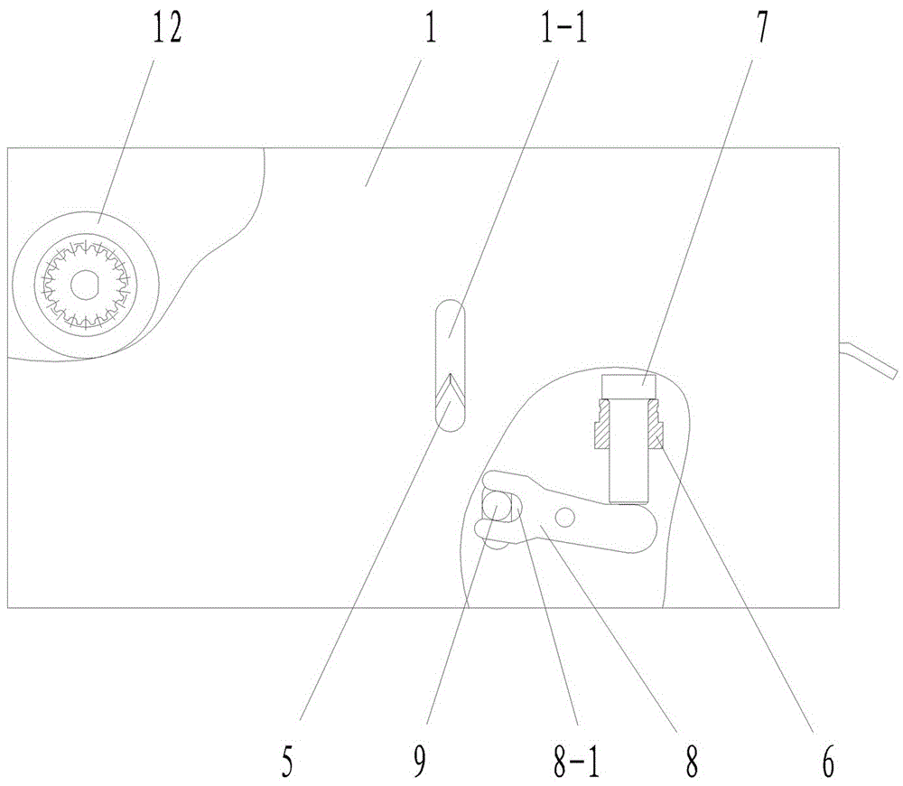
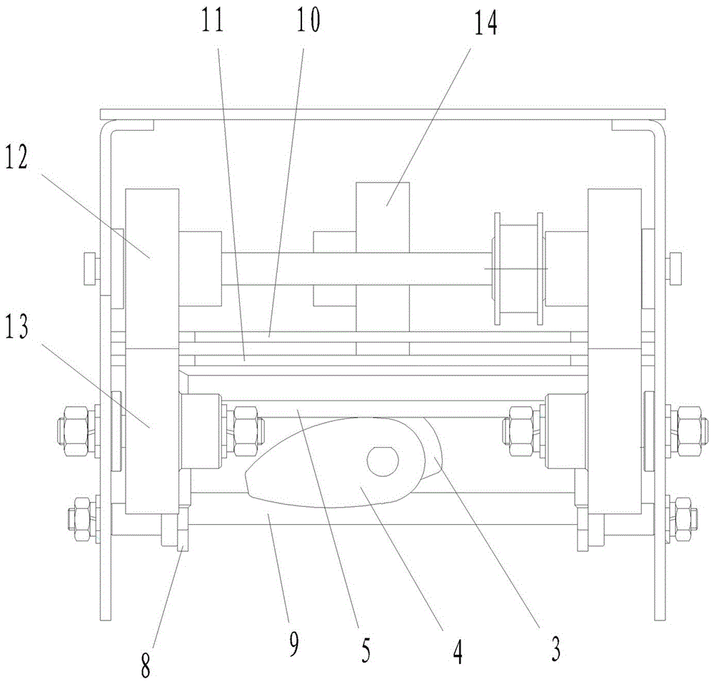
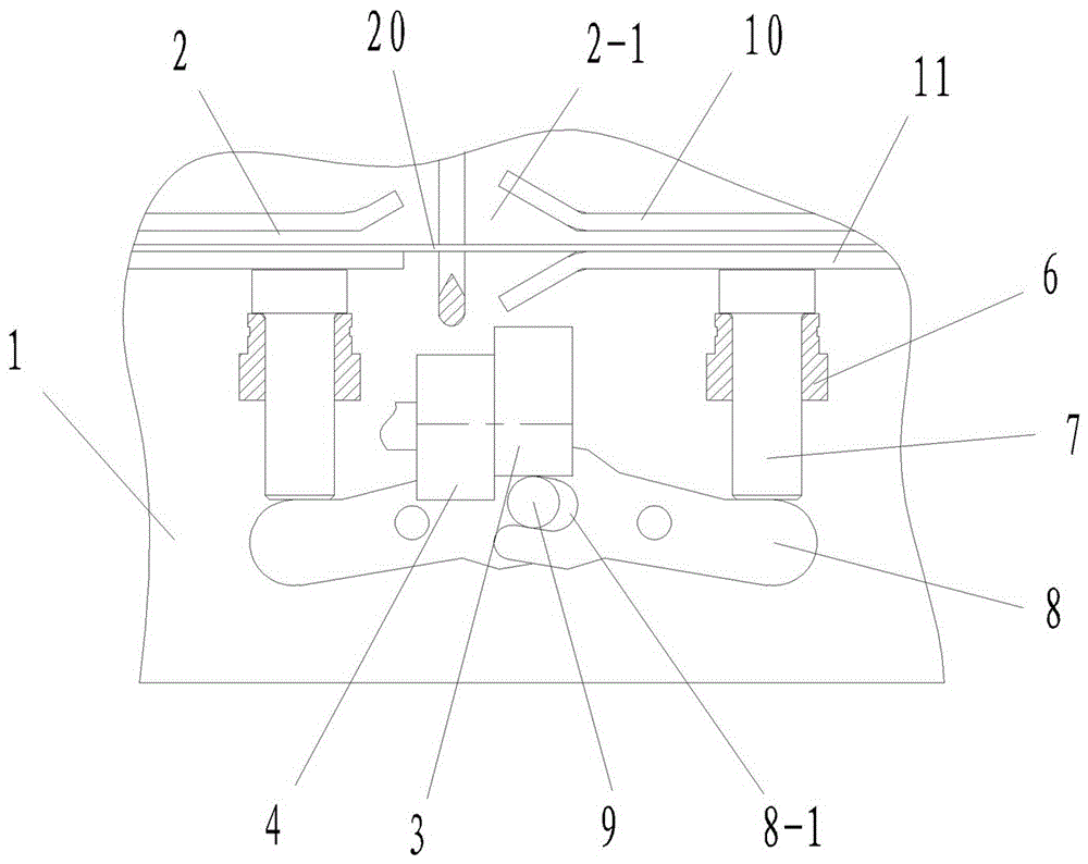
[0028] Example 1: See attached Figure 1-3 , The present invention provides a continuous bill single-sheet cutting machine, which includes a frame 1, a ticket belt conveying channel set on the frame 1, a ticket belt conveying mechanism, a ticket end pressing mechanism, and a bill cutting mechanism. :The ticket end pressing mechanism is provided with two sets and is located below the ticket belt conveying channel 2 and on both sides of the ticket dividing line. The ticket cutting mechanism includes a cutting knife 5 with a cutting edge arranged between the two sets of ticket end pressing mechanisms. And supporting drive mechanism. The slicing blade of the above-mentioned slicing knife 5 cuts one end of the bill with the aid of the slicing drive mechanism and moves to the other end to separate two connected bills.

[0029] See attached Figure 2-8 The two ends of the above-mentioned slicing knife 5 are slidably limited in the vertical slot 1-1 and the vertical slot 1-2 of the fram...

Embodiment 2

[0038] Example 2: See attached Picture 10 The difference from the first embodiment is that the dicing knife 5 is limited in the guide rail on the frame 1, and the dicing drive mechanism is a linear motor. Driven by a linear motor, the scribing knife 5 makes a reciprocating linear motion along the guide rail to achieve the purpose of scribing the bill. In this embodiment, in addition to a linear motor, a belt drive mechanism driven by a motor can also be used. The scoring knife 5 is fixed to the belt of the belt drive mechanism, and the scoring knife 5 is driven by the belt to perform a reciprocating linear motion to separate bills.


PUM


Abstract

The invention discloses a cutting machine for cutting continuous bills into single pieces and belongs to bill matching equipment. The cutting machine comprises a rack, a bill belt conveying channel, a bill belt conveying mechanism, bill end pressing mechanisms and a bill gashing mechanism, wherein the bill belt conveying channel, the bill belt conveying mechanism, the bill end pressing mechanisms and the bill gashing mechanism are arranged on the rack. The cutting machine is characterized in that the number of the bill end pressing mechanisms is two sets, and the bill end pressing mechanisms are located below the bill belt conveying channel and on the two sides of a bill dividing line; the bill gashing mechanism comprises a gashing knife and a matched gashing driving mechanism, and the cutting edge of the gashing knife is arranged between the two sets of bill end pressing mechanisms; and the gashing knife edge of the gashing knife gashes one ends of the bills and moves to the other ends of the bills with the help of the gashing driving mechanism to separate the two connected bills. The cutting machine for cutting the continuous bills into the single pieces has the beneficial technical effects that the two ends of the gashing knife are jacked up by a gashing driving cam successively, so that the gashing knife begins to gash from one sides of the bills and then moves to the other sides of the bills to complete dividing; the bills can also be separated in the mode that a linear motor and the like are adopted for driving the gashing knife; and after the bills are cut, the cut edges are smooth and neat.

Description

Technical field [0001] The invention belongs to bill management supporting equipment, and particularly relates to a continuous bill sheet cutting machine. Background technique [0002] Bills are paper prints with a certain size. The bills currently used are usually printed in multiple continuous strips in a roll shape, and the perforations punched out by the punching machine between each sheet form a cut line or an integrated structure , To tear apart a single bill during application, or cut two connected bills with the aid of a cutting mechanism. [0003] At present, the structure of the cutting machine on the market generally includes a ticket belt conveying channel, a ticket belt conveying mechanism, and a ticket cutting mechanism. When the bill reaches the slitting position, the cutting action is completed by the cutting mechanism, and finally the cut bill is sent out by the ticket belt conveying mechanism, and the next bill is transported to prepare for the next cutting. [00...

Claims


Application Information

Patent Timeline
Patent Type & Authority Patents(China)
IPC IPC(8): B26D1/10B26D5/16B26D7/06B26D7/27
CPCB26D1/105B26D5/16B26D7/02B26D7/0625B26D7/27
Inventor 孙景涛张宝石胡艾平
Owner HEBEI HUIJIN ELECTROMECHANICAL
Why Eureka
Try Eureka