Lip Type Seal

一种唇式密封、密封部件的技术,应用在发动机的密封、变容式泵部件、泵元件等方向,能够解决密封性能降低、密封唇75起泡等问题,达到提高耐起泡性的效果

Active Publication Date: 2016-07-20
EAGLE INDS
View PDF10 Cites 2 Cited by
  • Summary
  • Abstract
  • Description
  • Claims
  • Application Information

AI Technical Summary

Problems solved by technology

In the above-mentioned bonded lip seal under such use conditions, since the rubber-like elastic sealing lip 75 and the metal reinforcing ring 77 are bonded, when used under high-load conditions, the sealing lip 75 will be damaged. Blistering phenomenon, which becomes the cause of reduced sealing performance

Method used


Image

  • Lip Type Seal
  • Lip Type Seal
  • Lip Type Seal

Examples


no. 1 example

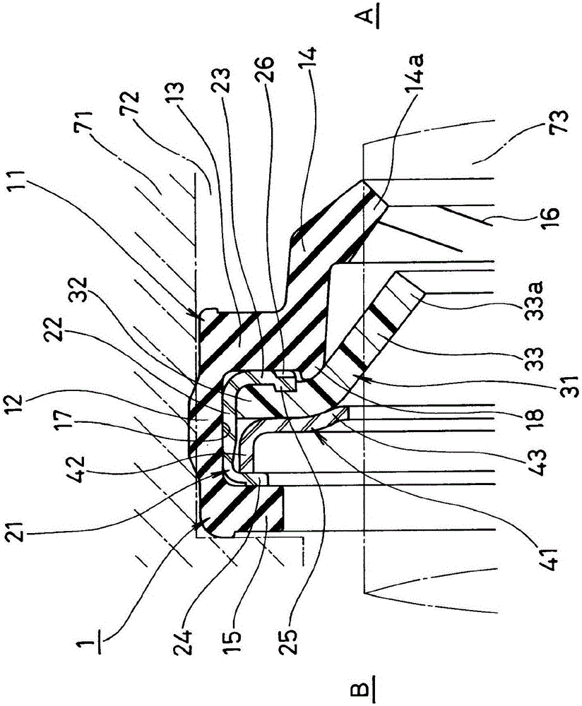
[0079] figure 1 A main part cross section of the lip seal 1 related to the first embodiment of the present invention is shown, and the lip seal 1 is configured as follows. In addition, this lip seal 1 is used as a water pump seal for automobiles to seal cooling water. The right side of the figure is the cooling water, that is, the seal fluid side A, and the left side of the figure is the atmospheric side B.

[0080] That is, the lip seal 1 is mounted on the inner periphery of the shaft hole (hole) 72 of the casing (pump casing) 71, and is slidably in close contact with the peripheral surface of the shaft (rotation shaft) 73, and is configured to have A double-layered lip structure of the rubber-like elastic sealing lip 14 on the fluid side A and the resin sealing lip 33 arranged on the atmospheric side B.

[0081] In addition, as the components of the lip seal 1, there are the following four parts: the first lip seal member 11 made of a rubber-like elastic body fitted in th...

no. 2 example

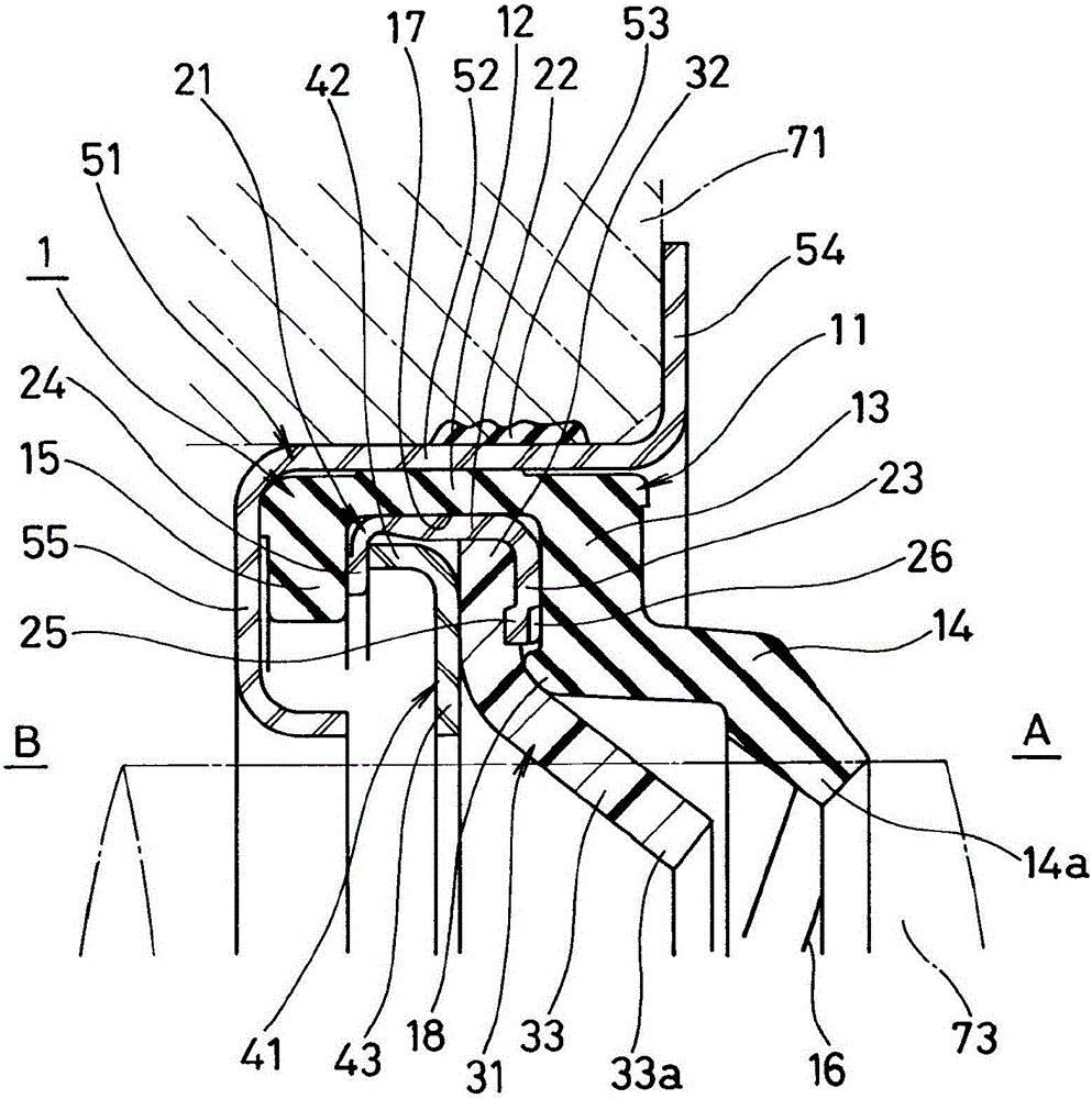
[0098] In addition, in the above-mentioned first embodiment, although the lip seal 1 is directly fitted into the inner periphery of the shaft hole 72 of the casing 71 through the cylindrical portion 12 of the first lip seal member 11, as figure 2 As shown, it can also be installed on the inner periphery of the shaft hole 72 of the casing 71 through the sleeve (metal ring) 51 .

[0099] figure 2 The shown sleeve 51 is made of a predetermined steel material such as metal, such as a stamped product of a metal plate, and is integrally formed into a ring shape. The lip seal 1 having the above-mentioned structure is fitted into the inner peripheral surface of the cylindrical portion 52, and the cylindrical portion 52 is sealed at the same time. The outer peripheral surface of the portion 52 is fitted into the inner peripheral surface of the shaft hole 72 of the casing 71 . The outer peripheral surface of the cylindrical portion 52 is covered with an outer peripheral seal 53 inter...

no. 3 example

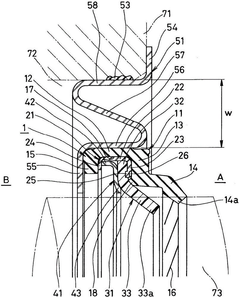
[0101] In addition, the sleeve 51 may be provided with a stepped shape in a planar shape at right angles to the axis on the cylindrical portion 52, or may be provided with a stepped shape with an S-shaped cross section on the cylindrical portion 52. In the above case, the size (diameter) of the sleeve 51 depends on The radial width of the stepped shape is formed in various ways. Therefore, when the lip seal 1 is installed on the actual machine, by selecting the sleeve 51 consistent with the shaft hole diameter of the actual machine, the lip seal 1 can be installed relative to shaft holes 72 of various sizes, thereby improving the lip seal 1. The versatility of type seal 1.

[0102] image 3 One example of a sleeve 51 of this type is shown, which is constructed as follows.

[0103] That is, the sleeve 51 is made of a predetermined steel material such as metal, such as a stamped product of a metal plate, is integrally formed in an annular shape, and has a small-diameter cylind...


PUM


Abstract

To facilitate recycling and prevent rotation of constituent parts, a lip type seal has a first lip seal member constructed from a rubber-like elastic material, a metal-made retaining ring held at the first lip seal member without bonding, and a resin-made second lip seal member and a backup ring which are held at the retaining ring by caulking. The first lip seal member has a tubular portion, a radial portion, a seal lip, and a collar portion. The retaining ring has a cylinder portion, a first flange portion, and a second flange portion, and the second lip seal member and the backup ring are held between the first and second flange portions by caulking. A convex portion is provided at a position in the circumferential direction of the first flange portion, and the convex portion engages with the second lip seal member to prevent rotation of the second lip seal member.

Description

[0001] This application is a divisional application of a PCT patent application in China with the Chinese patent application number 200980100552.7, the application date being April 6, 2009, and the invention name being "lip seal". technical field [0002] The present invention relates to a lip seal as a kind of sealing device. The lip seal of the present invention is used, for example, as a water pump seal for vehicles such as automobiles, or as other general general purpose water pump seals. Background technique [0003] Since before, as Figure 4 As shown, there is known a lip seal 74 installed on the inner periphery of the shaft hole 72 of the casing 71 and slidably in close contact with the peripheral surface of the shaft 73 inserted through the shaft hole 72. The lip seal 74 has a configuration The first seal lip 75 made of a rubbery elastic material is sealed on the fluid side A, and the second seal lip 76 made of resin is disposed on the air side B (see Patent Documen...

Claims


Application Information

Patent Timeline
Patent Type & Authority Applications(China)
IPC IPC(8): F16J15/3232F16J15/3228F16J15/3208F16J15/3268F04B53/00F16J15/3252
CPCF04B53/00F16J15/3208F16J15/3228F16J15/3268
Inventor 真田雅光板谷壮敏
Owner EAGLE INDS
Why Eureka
Try Eureka