
A mechanical hammer leveling device
A leveling and mechanical technology, applied in the direction of forming tools, metal processing equipment, manufacturing tools, etc., can solve the problems of high-efficiency surface quality and hardness metal mechanical hammer leveling technology, etc., to achieve good wear resistance and improve the surface Integrity, less tool wear effect
- Summary
- Abstract
- Description
- Claims
- Application Information
AI Technical Summary
Problems solved by technology
Method used
Image

Examples
Embodiment Construction
[0022] The present invention will be further described in detail below in conjunction with the accompanying drawings and specific embodiments.
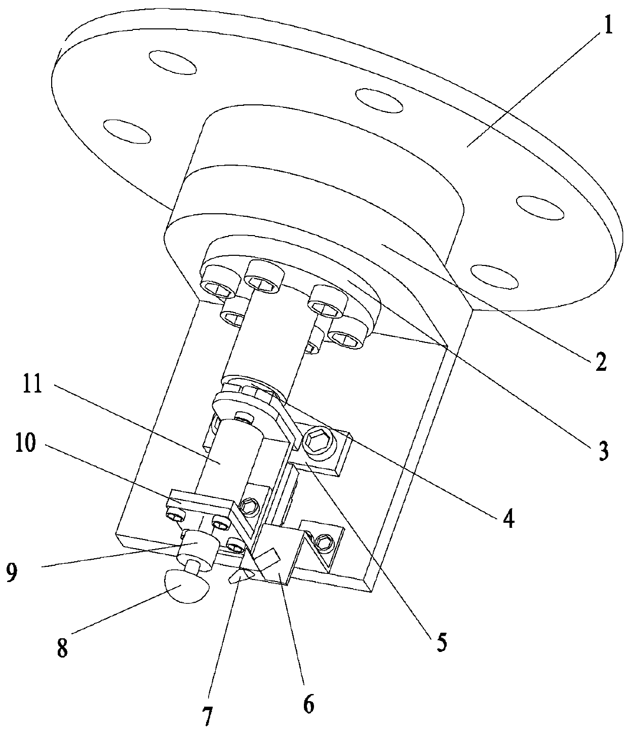
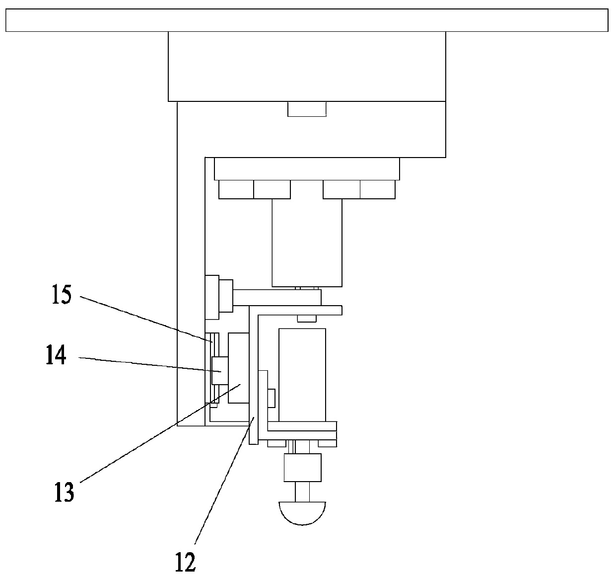
[0023] A mechanical hammer leveling device, including a connecting flange 1, an L-shaped plate 2, a fixed flange 3, a piezoelectric ceramic actuator 4, an anti-side plate 5, a Z-shaped plate 6, an air gun 7, and a hammering head 8 , adapter 9, motor fixing plate 10, motor 11, support frame 12, support plate 13, slide block 14 and slide rail 15.
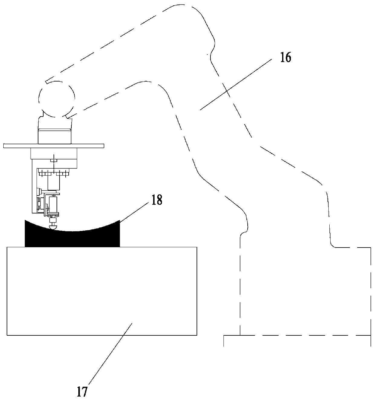
[0024] like figure 1 and 2 As shown, the connecting flange 1 is connected with the external flange through screws. The fixed flange 3 is fixed to the L-shaped plate 2 and the connecting flange 1 by screws, so the fixed flange 3, the L-shaped plate 2 and the connecting flange 1 are connected together. The fixed flange 3 is sleeved on the piezoelectric ceramic actuator 4 and closely matched. The piezoelectric ceramic actuator 4 is installed on the L-shaped plate 2 by screws. The anti-side ...
PUM
 Abstract
Description
Claims
Application Information