A curved U-shaped culvert structure

A curved and culvert technology, applied in the field of culvert structures, can solve problems such as subgrade erosion, short duration, and erosion, and achieve the effects of reducing stress concentration, reducing damage, and prolonging service life

Inactive Publication Date: 2018-09-21
CHONGQING JIAOTONG UNIVERSITY
View PDF6 Cites 0 Cited by
  • Summary
  • Abstract
  • Description
  • Claims
  • Application Information

AI Technical Summary

Problems solved by technology

In particular, highway culverts, as an important drainage system in transportation and one of the important structures to ensure that the subgrade is continuously protected from flood erosion or invasion, have a relatively high proportion of highway use in western regions; debris flows formed in western mountainous areas have the characteristics of sudden outbreaks, Due to the characteristics of short duration, ferocious onset and rapid disaster, a large amount of sources and huge energy accumulated in the early stage can be released in an instant when an eruption occurs, resulting in great destructive power. The area near the entrance of the culvert is the collection area of ​​debris flow, and the velocity and flow rate of the debris flow are very high. It is relatively large, so when a debris flow breaks out, it is often due to unreasonable design of the culvert, insufficient clearance of the culvert, or failure to take effective measures for the entrance and exit of the culvert and the bottom laying, resulting in serious erosion or silting blockage or deep erosion marks, endangering the overall stability of the culvert Sexual or even long-term interruption of the normal operation of traffic, resulting in a large area of ​​roadbed being washed away, etc.

Method used


Image

  • A curved U-shaped culvert structure
  • A curved U-shaped culvert structure
  • A curved U-shaped culvert structure

Examples


Embodiment approach 1

[0032] Embodiment 1: The curved bottom pavement structure adopts a semi-elliptical bottom pavement structure, which is specifically described as follows:

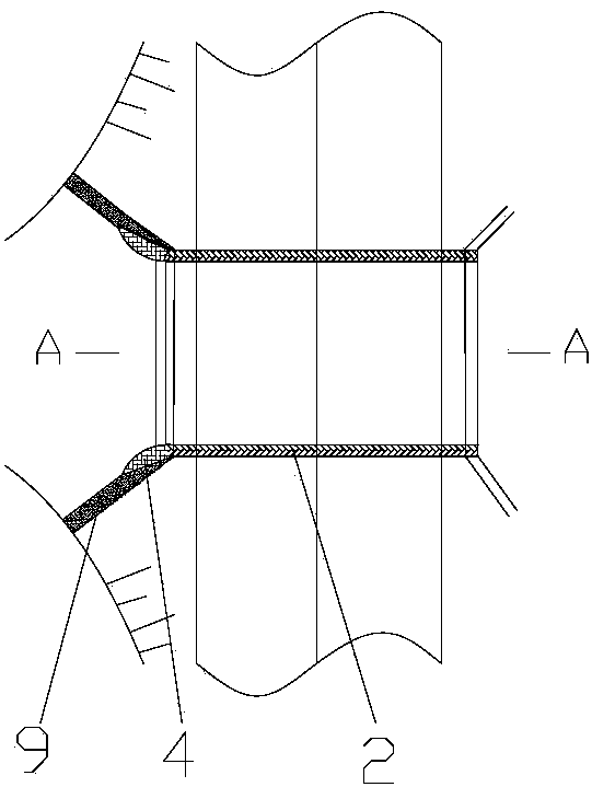
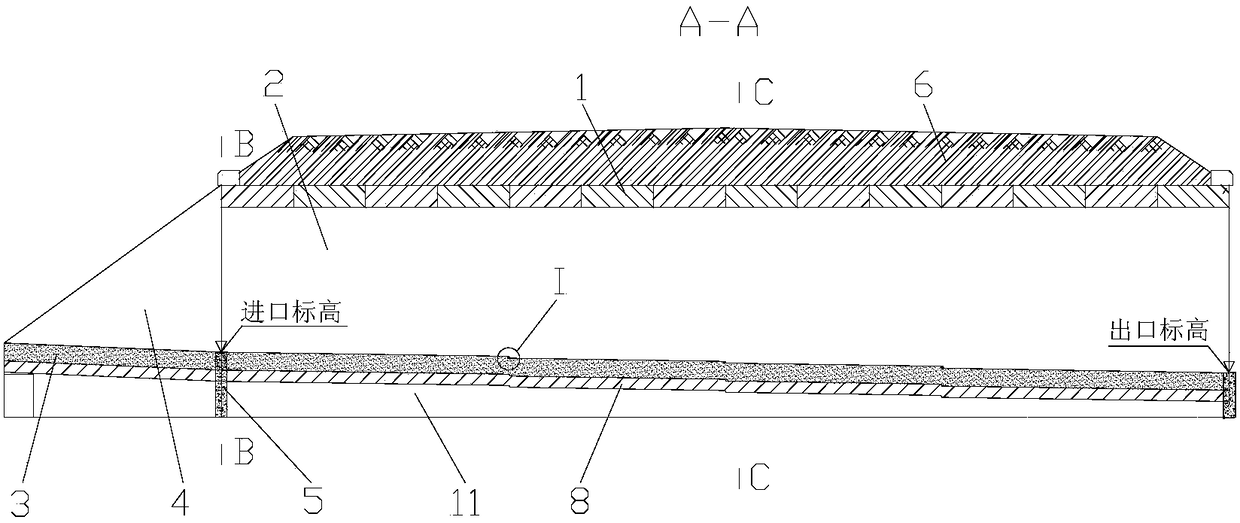
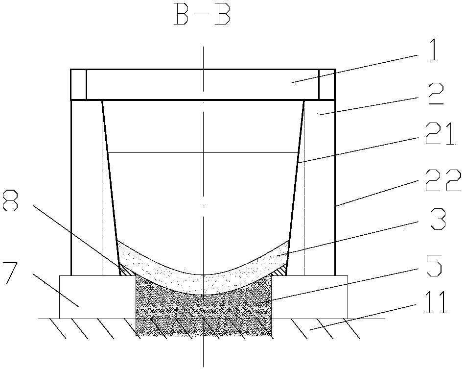
[0033] figure 1 It is a top view schematic diagram of a curved U-shaped culvert structure of the present invention, figure 2 It is a schematic cross-sectional view along A-A of a curved bottom U-shaped culvert structure of the present invention, image 3 It is a schematic cross-sectional view along B-B of a curved U-shaped culvert structure of the present invention, Figure 4 When adopting semi-elliptic bottom laying structure for a kind of curved bottom laying U-shaped culvert structure of the present invention along C-C sectional schematic diagram, Figure 7 It is a partially enlarged schematic diagram of a curved U-shaped culvert structure of the present invention. It can be seen from the figure that a curved U-shaped culvert structure includes a culvert body, a semi-elliptical bottom structure 31, a buffer layer 8, ...

Embodiment approach 2

[0044] Embodiment 2: The semicircular bottom paving structure adopts a semicircular bottom paving structure, which is specifically described as follows:

[0045] figure 1 It is a top view schematic diagram of a curved U-shaped culvert structure of the present invention, figure 2 It is a schematic cross-sectional view along A-A of a curved bottom U-shaped culvert structure of the present invention, image 3 It is a schematic cross-sectional view along B-B of a curved U-shaped culvert structure of the present invention, Figure 5 For a kind of curvilinear bottom laying U-shaped culvert structure of the present invention adopts semicircular bottom laying structure along C-C sectional schematic diagram, Figure 7 It is a partially enlarged schematic diagram of a curved U-shaped culvert structure of the present invention. It can be seen from the figure that a curved U-shaped culvert structure includes a culvert body, a semicircular bottom structure 32, a buffer layer 8, and a c...

Embodiment approach 3

[0056] Embodiment 3: The curved bottom pavement structure adopts a parabolic bottom pavement structure, which is specifically described as follows:

[0057] figure 1 It is a top view schematic diagram of a curved U-shaped culvert structure of the present invention, figure 2 It is a schematic cross-sectional view along A-A of a curved bottom U-shaped culvert structure of the present invention, image 3 It is a schematic cross-sectional view along B-B of a curved U-shaped culvert structure of the present invention, Image 6 When adopting parabolic bottom laying structure for a kind of curved bottom laying U-shaped culvert structure of the present invention along C-C sectional schematic diagram, Figure 7 It is a partially enlarged schematic diagram of a curved U-shaped culvert structure of the present invention. It can be seen from the figure that a curved U-shaped culvert structure includes a culvert body, a parabolic bottom structure 33, a buffer layer 8, and a culvert ent...


PUM


Abstract

Many debris flow areas exist in West China, direct impact and undercutting by debris flow are the important acting force types for damage to ridges and culverts, and reasonably selecting the structural mode of a passage cross section for a culvert in a debris flow area and making sure that the structural mode can help the roadbed culvert achieve good impact resistance and optimal discharging capacity under the situation of limited terrains are important issues needing to be taken into consideration when a novel culvert in the debris flow area is designed. The invention provides a U-shaped culvert structure with curved bottoming structures. The U-shaped culvert structure comprises a culvert body, the curved bottoming structures, a buffer layer and a culvert inlet. The culvert body comprises a thickened cover plate, trapezoid culvert side plates and culvert foundations. The culvert foundations and the trapezoid culvert side plates are arranged on the two sides of the U-shaped culvert. One curved bottoming structure is arranged at the bottom between the trapezoid culvert side plates on the two sides. The thickened cover plate is arranged on the top between the trapezoid culvert side plates on the two sides. The culvert inlet comprises an inlet conical revetment, an inlet convergence trough and the other curved bottoming structure.

Description

technical field [0001] The invention relates to a culvert structure for highways spanning small and medium-sized mud-rock flow ditches, in particular to a curved U-shaped culvert structure with a bottom pavement. Background technique [0002] With the gradual implementation of the national "Belt and Road" development strategy in the 21st century and the in-depth promotion of the western development strategy, the western region will show the latecomer advantage of opening up to the outside world, and the investment and construction of transportation infrastructure in the western region will become the focus of improving people's livelihood in my country. There are many debris flow areas in the western region, where the rock formations are broken, the earthquake intensity is large, the damage area is wide, the vegetation is less, and there are heavy rains in summer, coupled with the continuous expansion of human activities, it breeds frequent occurrence of debris flow disasters...

Claims


Application Information

Patent Timeline
Patent Type & Authority Patents(China)
IPC IPC(8): E01F5/00
CPCE01F5/005
Inventor 丁静声袁猛张铭
Owner CHONGQING JIAOTONG UNIVERSITY
Why Eureka
Try Eureka