Electrical connectors for circuit boards

A technology for circuit substrates and electrical connectors, applied in the direction of conductive connections, connections, circuits, etc., can solve problems such as scratches on the inner surface, and achieve the effects of stabilizing the shell, preventing damage, and improving strength

Active Publication Date: 2019-07-16
HIROSE ELECTRIC GROUP
View PDF6 Cites 0 Cited by
  • Summary
  • Abstract
  • Description
  • Claims
  • Application Information

AI Technical Summary

Problems solved by technology

In Patent Document 1, since the inner surface of the end wall is not covered by the reinforcing metal fitting, the fitting portion of the plug connector directly abuts against the inner surface of the end wall, which may cause damage such as scratches on the inner surface.

Method used


Image

  • Electrical connectors for circuit boards
  • Electrical connectors for circuit boards
  • Electrical connectors for circuit boards

Examples


Embodiment Construction

[0024] Hereinafter, embodiments of the present invention will be described based on the drawings.

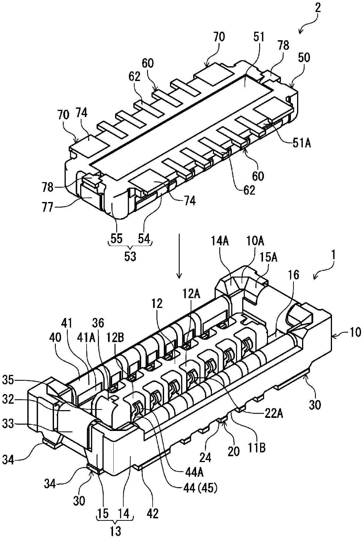
[0025] figure 1 It is a perspective view of the receptacle connector of this embodiment and the plug connector which is a target connector mated with it from above, and shows the state before connector mating. The receptacle connector 1 and the plug connector 2 of this embodiment are electrical connectors for circuit boards arranged on the mounting surfaces of different circuit boards (not shown), respectively, and are configured such that they are arranged in a direction at right angles to the mounting surfaces of the respective circuit boards. ( figure 1 The up and down direction in) becomes the connector assembly in the plugging and unplugging direction. In this embodiment, the fitting direction of the plug connector 2 with respect to the receptacle connector 1, that is,figure 1 The direction in which the plug connector 2 moves downward is referred to as the "connector fitt...


PUM


Abstract

The present invention provides an electrical connector for a circuit board that can prevent damage to both the protruding wall and the outer wall of the housing during the connector insertion and extraction process. The casing has a bottom wall (11) facing the mounting surface of the circuit board, a pair of outer walls (15) standing up from opposite edge portions of the bottom wall, and a pair of outer walls (15) standing up from the bottom wall between the pair of outer walls. The protruding wall, in the above-mentioned electrical connector for circuit boards, the reinforcing metal fitting has: an outer wall rising surface reinforcement extending along the rising surface of the outer wall opposite to the rising surface of the protruding wall (12) and being held by the outer wall. (31), a protruding wall rising surface reinforcing portion (35) extending along the rising surface of the protruding wall (12) opposite to the outer wall rising surface reinforcing portion and being held by the protruding wall, and along the bottom wall The connection bottom (38) extends and connects the bottom wall side ends of the outer wall rising surface reinforcement part and the protruding wall rising surface reinforcement part to each other.

Description

technical field [0001] The present invention relates to an electrical connector for a circuit board arranged on a mounting surface of a circuit board. Background technique [0002] As such an electrical connector for a circuit board, for example, a receptacle connector of Patent Document 1 is known. In the receptacle connector of Patent Document 1, a plurality of terminals arranged in a direction parallel to the mounting surface of the circuit board as the terminal arrangement direction, and reinforcing metal fittings arranged at positions outside the terminal arrangement range in the terminal arrangement direction It is held by integral molding with a resin case. The housing has: a bottom wall parallel to the mounting surface, a protruding wall rising from the bottom wall and extending along the terminal arrangement direction, and a peripheral wall standing from the bottom wall surrounding the protruding wall. The peripheral wall has a pair of side walls as outer walls ex...

Claims


Application Information

Patent Timeline
Patent Type & Authority Patents(China)
IPC IPC(8): H01R12/70H01R13/46
CPCH01R12/70H01R12/7011H01R12/73H01R4/028H01R12/57H01R12/707H01R12/7082H01R12/71H01R12/716H01R13/6275
Inventor 小林勇貴
Owner HIROSE ELECTRIC GROUP
Why Eureka
Try Eureka