Loop layout of reactor coolant for passive pressurized water reactor nuclear power plant

A technology for pressurized water reactor nuclear power plants and reactors, applied in the directions of reactors, cooling devices, nuclear power plant auxiliary equipment, etc., can solve problems such as the difficulty of main pump development, and achieve the effects of avoiding development problems, improving localization rate, and saving construction costs.

Pending Publication Date: 2016-11-09
SHANGHAI NUCLEAR ENG RES & DESIGN INST CO LTD
View PDF6 Cites 1 Cited by
  • Summary
  • Abstract
  • Description
  • Claims
  • Application Information

AI Technical Summary

Problems solved by technology

At present, it is very difficult to develop the main pump of the AP1000 nuclear power plant in the world. If a nuclear power plant with a higher power than the AP1000 is to be developed, it is necessary to develop a main pump with a higher power than the AP1000 nuclear power plant.

Method used


Image

  • Loop layout of reactor coolant for passive pressurized water reactor nuclear power plant
  • Loop layout of reactor coolant for passive pressurized water reactor nuclear power plant

Examples


Embodiment Construction

[0043] In order to make the above objects, features and advantages of the present invention more comprehensible, the present invention will be further described in detail below in conjunction with the accompanying drawings and specific embodiments.

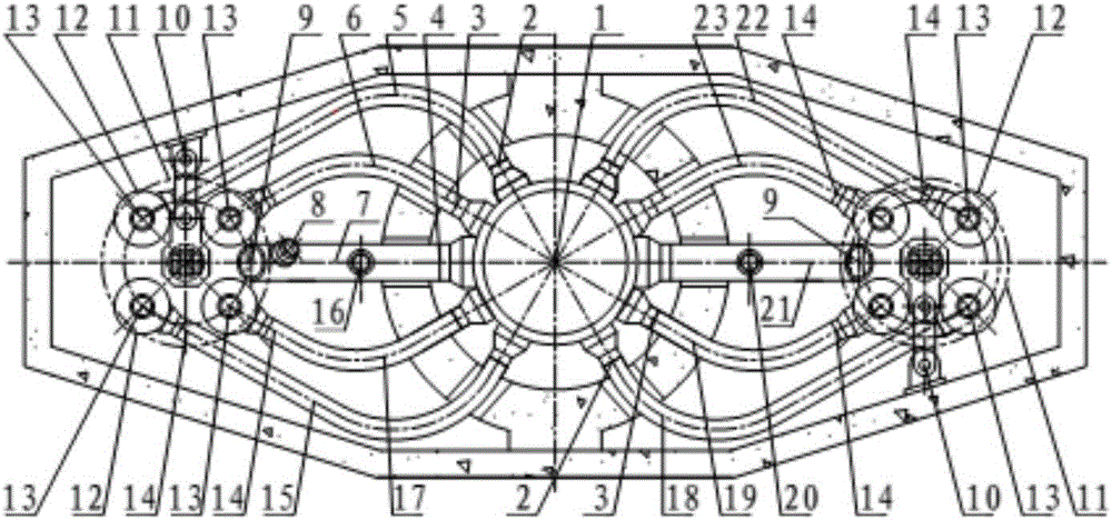
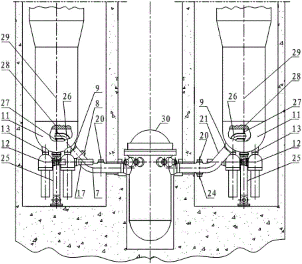
[0044] like figure 1 and 2 As shown, it is the layout of the reactor coolant loop of the passive PWR nuclear power plant, including:

[0045] 1. Reactor pressure vessel:

[0046] Under the condition that the opening of the reactor pressure vessel connecting section cylinder (see item 1) is allowed, two reactor coolant outlet nozzles (see item 4) are arranged on the reactor pressure vessel connecting section cylinder to connect two main pipes The hot section (see item 7 or item 21), and eight reactor coolant inlet nozzles (see item 2 or item 3) are used to connect the cold sections of the eight main pipes (see item 5, item 6, item 15 , Item 17 or see Item 18, Item 19, Item 22, Item 23). Two reactor coolant outlet nozzles are ar...


PUM


Abstract

The invention provides a loop layout of a reactor coolant for a passive pressurized water reactor nuclear power plant. The loop layout comprises a reactor pressure vessel and a vapor generator, wherein the reactor pressure vessel comprises a pipe connecting section cylinder, and the pipe connecting section cylinder is provided with a reactor coolant outlet pipe connecting mouth and a reactor coolant inlet pipe connecting mouth; and the vapor generator is connected with the reactor pressure vessel through a main pipeline. According to the loop layout, the design of a reactor coolant loop is improved, so that the difficulty of the technological development bottleneck of large-scale main pumps of large-scale CAP series nuclear power plants is broken through, two main coolant loops are realized under the condition that a main pump with the power higher than that of a CAP1000 nuclear power plant is not utilized and even the main pump with the power lower than that of the CAP1000 nuclear power plant is used, and meanwhile, CAP series passive pressurized nuclear power plants with power higher than that of the CAP1000 nuclear power plant are realized.

Description

technical field [0001] The invention relates to the field of pressurized water reactor nuclear power plants, in particular to an arrangement of reactor coolant loops in passive nuclear power plants. Background technique [0002] The third-generation passive nuclear power plants of the CAP series, represented by the CAP1000 nuclear power plant, have become the main reactor types for my country's nuclear power development. The reactor main coolant system of CAP1000 nuclear power plant adopts two-loop arrangement, and each loop consists of one hot section of the main pipe that transfers the reactor coolant from the reactor pressure vessel to the steam generator and two pipes that transfer the reactor coolant from the reactor main cooling The agent pump (referred to as the main pump) is composed of the cold section of the main pipeline that returns to the reactor pressure vessel. The inlet nozzle of each main pump is directly connected with the outlet nozzle of the steam genera...

Claims


Application Information

Patent Timeline
Patent Type & Authority Applications(China)
IPC IPC(8): G21C15/12G21C15/14G21D1/00G21D1/02
CPCG21C15/12G21C15/14G21D1/006G21D1/02Y02E30/30Y02E30/00
Inventor 施永兵
Owner SHANGHAI NUCLEAR ENG RES & DESIGN INST CO LTD
Why Eureka
Try Eureka