Screw extractor for orthopedic surgery

A technology of orthopedic surgery and nail tube, which is applied in the field of orthopedic surgery nail remover, can solve the problems of patients' pain, inability to remove bone nails, and high bone destruction, so as to improve operation efficiency, prevent screw chute, and relieve pain Effect

Active Publication Date: 2016-12-07
SUZHOU SUNAN ZIMMERED MEDICAL INSTR
View PDF6 Cites 22 Cited by
  • Summary
  • Abstract
  • Description
  • Claims
  • Application Information

AI Technical Summary

Problems solved by technology

Firstly, the screw needs to be taken out after the patient recovers. The structural limitations of ordinary screwdriver tools can only rotate the hollow screw. The bone density of elderly patients is low, and it is difficult to form threads on the bone, so that the bone screw cannot be taken out; secondly, , some bone nails are tightly combined with the bone, which can easily cause damage to the bone nail cap; again, the use of forceps extractor is more destructive to the bone, causing unnecessary pain to the patient
[0003] In the prior art, the bone screw extractor often has the damage to the chute due to excessive force on the screw tail cap, or when the screw rotates in the opposite direction, after turning to a certain position, it cannot continue to be screwed out, and can only be idling on the spot. The phenomenon of half-threaded cancellous bone screws and half-threaded hollow screws is more obvious; this situation leads to the fact that some patients cannot even take out the bone screws after the fracture heals, but can only remain in the body, causing physical and psychological distress for patients

Method used


Image

  • Screw extractor for orthopedic surgery

Examples


Embodiment Construction

[0019] The following will clearly and completely describe the technical solutions of the embodiments of the present invention with reference to the accompanying drawings of the embodiments of the present invention. Obviously, the described embodiments are only some of the embodiments of the present invention, not all of them. Based on the embodiments of the present invention, all other embodiments obtained by persons of ordinary skill in the art without creative efforts fall within the protection scope of the present invention.

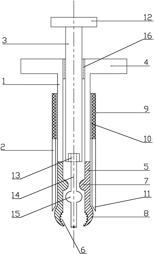
[0020] according to figure 1 , the present invention provides a nail remover for orthopedic surgery, comprising a nail removal tube 1, a holding tube 2, a dilator 3, a handle 4, a holding clip 5, conical teeth 6, tooth clip protrusions 7, an arc clip Head 8, anti-skid handle 9, fastening thread 10, inner tapered nozzle 11, handle 12, clip joint 13, batch rod 14, expansion ball joint 15, limit thread 16.

[0021] The inside of the nail-taking tube 1 i...


PUM


Abstract

The invention discloses a screw extractor for an orthopedic surgery. The screw extractor comprises a screw extracting tube, holding tubes, a dilator, holding clamps, conical teeth, tooth clamp convex sections, arc-shaped chucks, a driver bar and a dilating ball joint, wherein the dilator is arranged in the screw extracting tube through limit threads in a screwing manner; the holding tubes are arranged at the outer part of the screw extracting tube through fastening threads; handles are arranged at the outer sides of the upper end of the screw extracting tube, and the limit threads are arranged at the inner side of the upper end of the screw extracting tube; a plurality of holding clamps and holding clamp grooves are arranged at and formed in the lower end of the screw extracting tube; the arc-shaped chucks and the conical teeth are arranged at the lower ends of the corresponding holding clamps; one tooth clamp convex section is arranged at the inner side of each holding clamp; the driver bar is arranged at the lower end of the dilator; the dilating ball joint is arranged in the middle of the dilator; the dilating ball joint is moved by the dilator through the limit threads; the dilating ball joint pushes away the tooth clamp convex sections and drives the holding clamps to dilate; a bone screw cap is clamped and fixed by the plurality of arc-shaped chucks. According to the screw extractor disclosed by the invention, the screw cap is fixed by the arc-shaped chucks and the conical teeth; screws can be quickly and conveniently taken out and are prevented from sliding out of the groove, so that pains of a patient are relieved, and the efficiency of the surgery is improved.

Description

technical field [0001] The invention relates to the field of orthopedic appliance technical equipment, in particular to a nail remover for orthopedic surgery. Background technique [0002] In orthopedic surgery, internal fixation with screws combined with steel plates and hollow screws is a common method, especially half-threaded cancellous bone screws and half-threaded hollow screws are more widely used. After the fracture is fixed, it can reach a stable state and meet the intensity of rehabilitation training, combined with early functional exercise to promote fracture healing. Firstly, the screw needs to be taken out after the patient recovers. The structural limitations of ordinary screwdriver tools can only rotate the hollow screw. The bone density of elderly patients is low, and it is difficult to form threads on the bone, so that the bone screw cannot be taken out; secondly, , part of the bone nail is closely combined with the bone, which is easy to cause damage to th...

Claims


Application Information

Patent Timeline
Patent Type & Authority Applications(China)
IPC IPC(8): A61B17/92
Inventor 钱俊
Owner SUZHOU SUNAN ZIMMERED MEDICAL INSTR
Why Eureka
Try Eureka