

Rotating gluing mechanism for cylinder packaging barrel
A technology of packaging barrels and gluing, which is applied in the direction of coating, devices for coating liquid on the surface, etc., which can solve the problems of physical exertion, troublesome manual packaging, and low efficiency.
- Summary
- Abstract
- Description
- Claims
- Application Information
AI Technical Summary
Problems solved by technology
Method used
Image

Examples
Embodiment
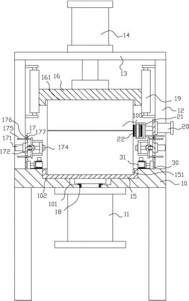
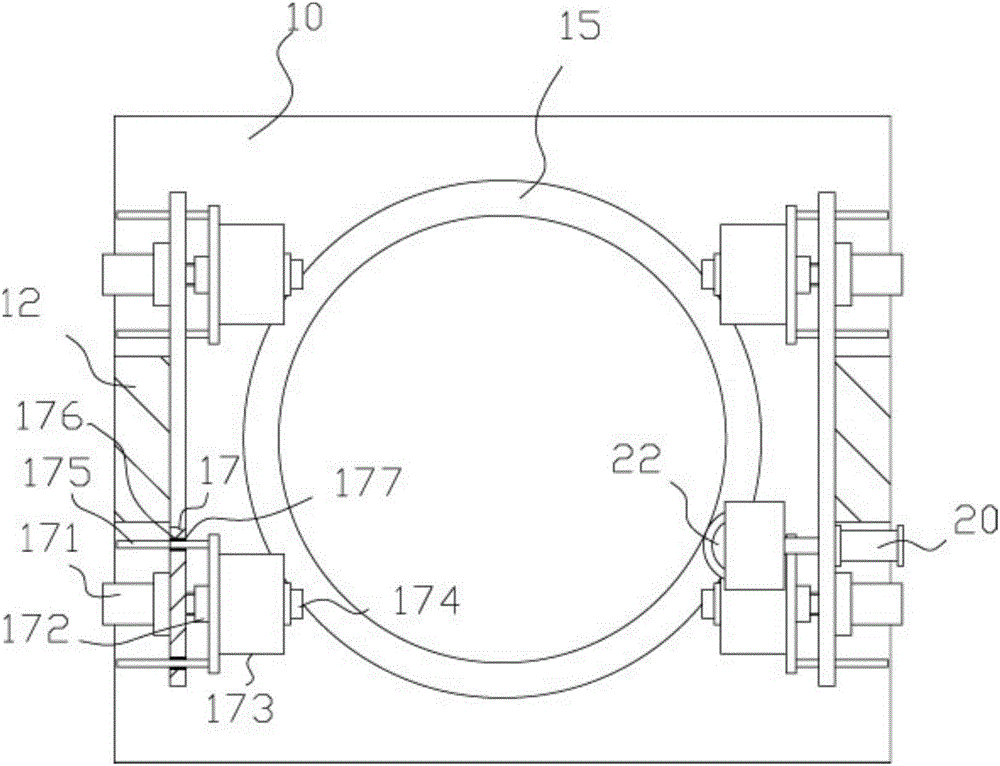
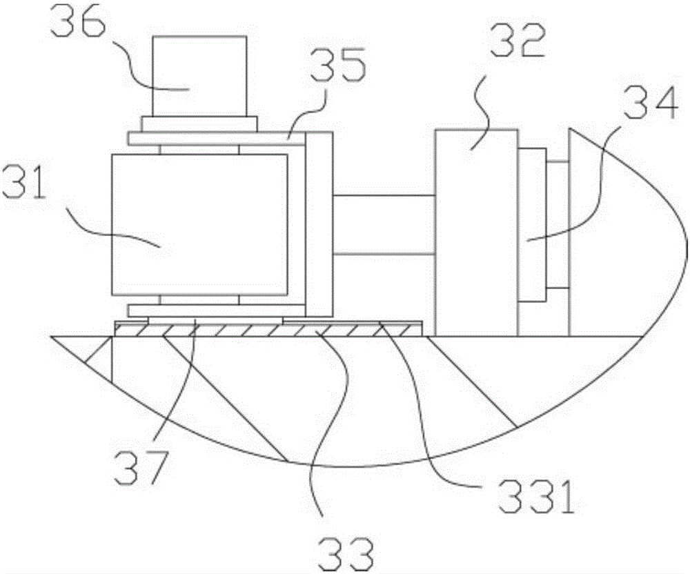
[0023] Example: see Figure 1 to Figure 4 As shown in the figure, a cylindrical packaging drum rotating glue application mechanism includes a clamping frame 10, which is characterized in that: the middle part of the bottom surface of the top plate of the clamping frame 10 is fixed with a lower clamping cylinder 11, and the edge of the top plate of the clamping frame 10 is fixed Vertical plate 12 is arranged, and upper plate body 13 is fixed on the top of two vertical plates 12, and upper clamping cylinder 14 is fixed on the top surface middle part of upper plate body 13, and the left and right sides of the top plate of clamping frame 10 are provided with drive means 30;
[0024] The push rod of the lower clamping cylinder 11 is inserted in the stepped hole 101 that the bottom surface of the top plate middle part of the clamping frame 10 has. The stepped hole 101 communicates, the lower clamping plate 15 is inserted in the circular groove 102 and pressed against the bottom sur...
PUM
 Abstract
Description
Claims
Application Information