High-speed precision film lamination equipment

A kind of film sticking equipment and sophisticated technology, applied in the direction of transportation and packaging, packaging, chemical instruments and methods, etc., can solve problems such as difficult operation, difficult to widely apply to small and medium-sized enterprises, and decline in film quality, so as to improve position accuracy and improve film sticking Efficiency and the effect of reducing the scrap rate

Active Publication Date: 2019-01-15
CHENGDU HOMIN TECH
View PDF5 Cites 0 Cited by
  • Summary
  • Abstract
  • Description
  • Claims
  • Application Information

AI Technical Summary

Problems solved by technology

[0003] The traditional method of sticking protective film on the surface of the product is to fix the product on the working platform first, cover the protective film on the product and straighten it, and then roll the protective film with a roller to make the protective film stick to the product smoothly , and then cut the protective film with a blade. This method of pasting the film is time-consuming and laborious, and the work efficiency is low. Moreover, it is easy to form air bubbles between the protective film and the product due to uneven rolling of the rollers, and the quality of the film is reduced. The manual film is low in precision. , even small electronic products cannot be filmed
In recent years, automatic film laminating equipment has gradually appeared in large enterprises, but its complex structure, difficult operation, and high maintenance costs make it difficult to be widely used in small and medium-sized enterprises

Method used


Image

  • High-speed precision film lamination equipment
  • High-speed precision film lamination equipment
  • High-speed precision film lamination equipment

Examples


Embodiment Construction

[0023] The present invention will be further described below in conjunction with the accompanying drawings, but the protection scope of the present invention is not limited to the following description.

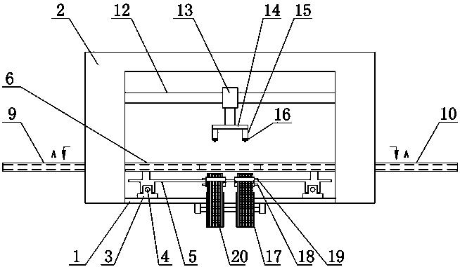
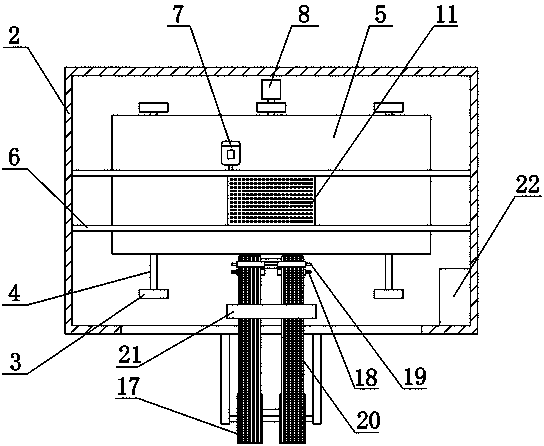
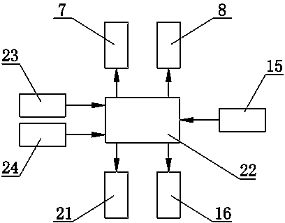
[0024] Such as figure 1 with figure 2 As shown, the high-speed precision film laminating equipment includes a base 1, a feeding mechanism, a film feeding mechanism, a film suction mechanism and a controller 22. The feeding mechanism is arranged along the length direction of the base 1, and the film suction mechanism is installed on the base 1. And the film suction mechanism is located above the feeding mechanism, and the film feeding mechanism is arranged on one side of the base 1. The feeding mechanism includes a moving support 3, a longitudinal moving plate 5 and a lateral moving carriage 6, and two groups of moving supports 3 Symmetrically fixed on the base 1, each group of moving supports 3 is equipped with a longitudinal guide rail 4, the longitudinal guide plate 5 is ...


PUM


Abstract

The invention relates to high-speed precision film attaching equipment. The high-speed precision film attaching equipment comprises a base, a feeding mechanism, a film delivering mechanism, a film suction mechanism and a controller. The feeding mechanism is arranged in the length direction of the base. The film suction mechanism is mounted on the base and located above the feeding mechanism. The film delivering mechanism is arranged at one side of the base. The feeding mechanism comprises movable supports, a longitudinal movement plate and a transverse movement sliding bracket. The two movable supports are symmetrically fixed to the base. A longitudinal movement guide rail is mounted on each movable support. The longitudinal movement plate is mounted on the longitudinal movement guide rails in a sliding-fit manner. The transverse movement sliding bracket is fixed to the longitudinal movement plate and internally provided with a material containing box in a matched manner. The film delivering mechanism comprises film delivering rollers, film carrying belts and a dragging mechanism. The film suction mechanism comprises a movable support, a slide block, CCD cameras and material suction air cylinders. The controller is connected with a transverse movement servo driving mechanism, a longitudinal movement servo driving mechanism, the CCD cameras, the material suction air cylinders and a material dragging mechanism. The high-speed precision film attaching equipment has the beneficial effects of being high in film attaching efficiency and precision.

Description

technical field [0001] The invention relates to the technical field of film sticking of electronic components, in particular to high-speed precision film sticking equipment. Background technique [0002] Electronic components are the foundation of the information industry and belong to the high-tech industry with broad prospects for development. In the next few years, miniaturization will still be one of the most important development trends of electronic components. The processing technology of electronic components is also more and more people's attention. During the stamping and forming process of electronic components, small particles of debris will be generated. In order to prevent the debris from contaminating or damaging electronic components, a protective film is usually attached to the surface of electronic components. [0003] The traditional method of sticking protective film on the surface of the product is to fix the product on the working platform first, cove...

Claims


Application Information

Patent Timeline
Patent Type & Authority Patents(China)
IPC IPC(8): B32B37/00B65B33/02B65B41/06B65B57/00
CPCB65B33/02B65B41/06B65B57/00
Inventor 刘呈明罗建国王军涛
Owner CHENGDU HOMIN TECH
Why Eureka
Try Eureka