A cable type welding wire applied to cmt welding system and cmt welding system

A welding system and cable-type welding wire technology, applied in welding equipment, welding medium, welding equipment, etc., can solve the problems of limited welding wire diameter and low efficiency, achieve good welding effect, reduce costs, and reduce production costs.

Active Publication Date: 2018-10-12
QINGDAO BRANCH CO., LTD. OF MECHANICAL SCIENCE RESEARCH INSTITUTE
View PDF5 Cites 0 Cited by
  • Summary
  • Abstract
  • Description
  • Claims
  • Application Information

AI Technical Summary

Problems solved by technology

However, the efficiency of the filling process in thick plates is very low, which is caused by factors such as the limited diameter of the welding wire

Method used


Image

  • A cable type welding wire applied to cmt welding system and cmt welding system
  • A cable type welding wire applied to cmt welding system and cmt welding system

Examples


Embodiment 1

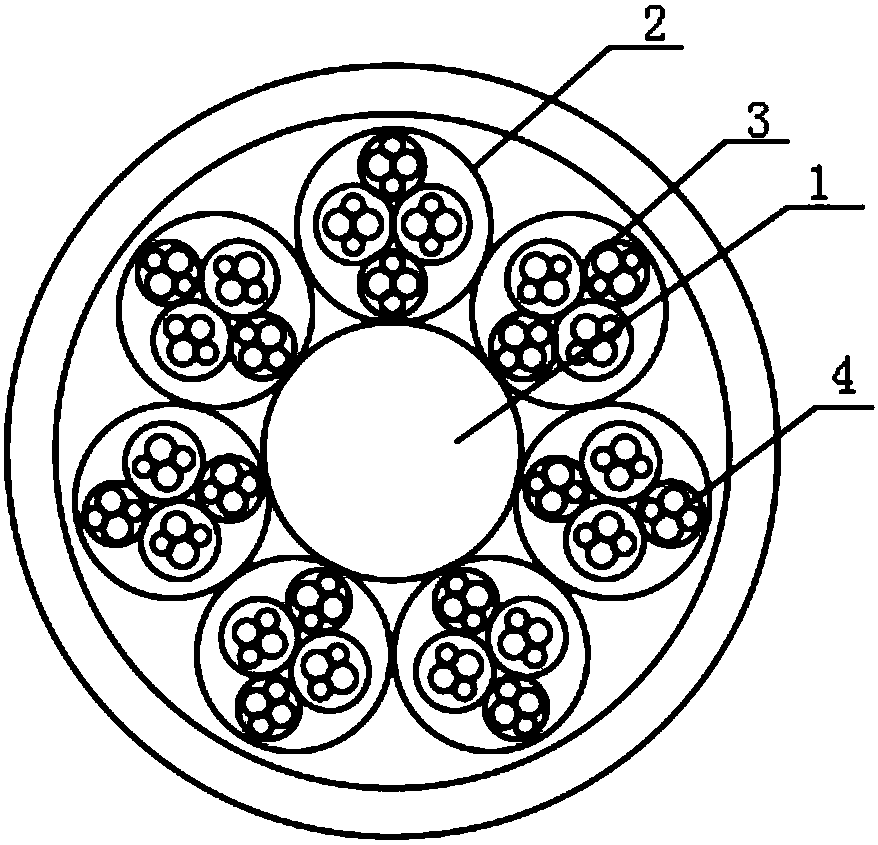
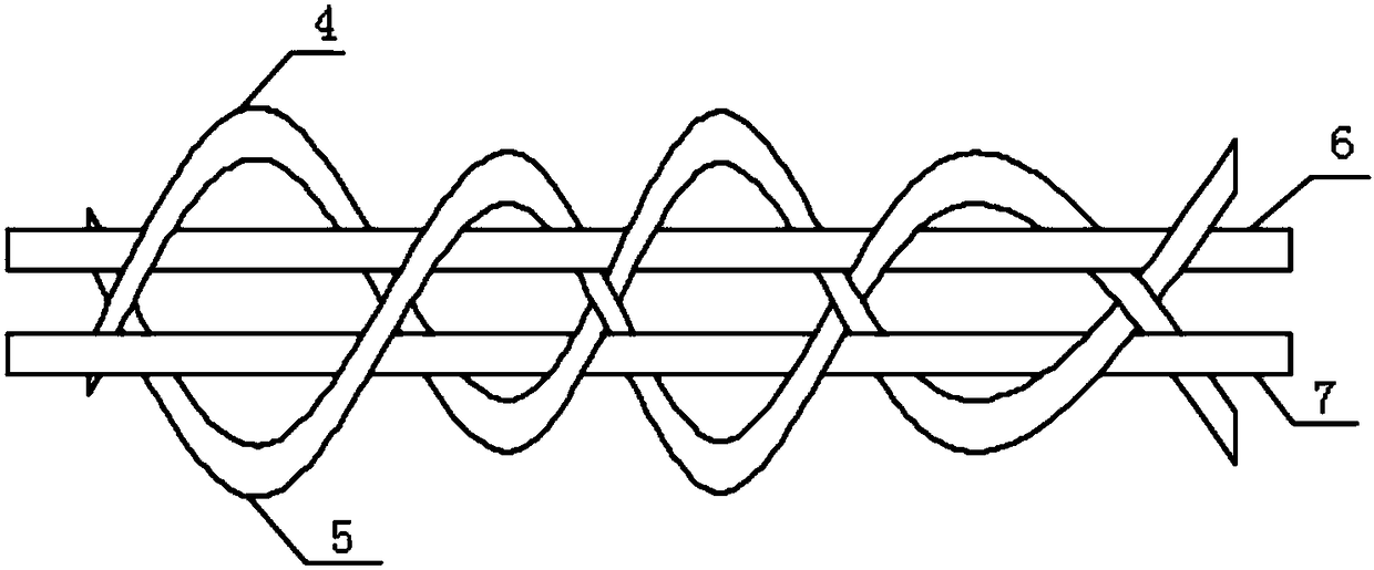
[0015] See Figure 1-2 , The present invention provides a technical solution: a cable type welding wire applied to a CMT welding system, comprising a central welding wire 1, a spiral welding wire 2 is arranged on the outer side of the central welding wire 1, and the spiral welding wire 2 is tightly wound around the central welding wire in a spiral manner 1 and the outer side of the spiral welding wire 2 is provided with a protective ring, the spiral welding wire 2 is provided with four sets of sub-welding wire groups 3, and the sub-welding wire groups 3 are arranged tangentially, and the sub-welding wire groups 3 There are first welding wire 4, second welding wire 5, third welding wire 6 and fourth welding wire 7 inside. The diameters of the first welding wire 4 and the second welding wire 5 are D, the third welding wire 6 and the fourth welding wire The diameter of 7 is d, and d is smaller than D. The spiral welding wire 2 is seven strands, and the seven spiral welding wires 2...

Embodiment 2

[0021] See Figure 1-2 , The present invention provides a technical solution: a cable type welding wire applied to a CMT welding system, comprising a central welding wire 1, a spiral welding wire 2 is arranged on the outer side of the central welding wire 1, and the spiral welding wire 2 is tightly wound around the central welding wire in a spiral manner 1 and the outer side of the spiral welding wire 2 is provided with a protective ring, the spiral welding wire 2 is provided with four sets of sub-welding wire groups 3, and the sub-welding wire groups 3 are arranged tangentially, and the sub-welding wire groups 3 There are first welding wire 4, second welding wire 5, third welding wire 6 and fourth welding wire 7 inside. The diameters of the first welding wire 4 and the second welding wire 5 are D, the third welding wire 6 and the fourth welding wire The diameter of 7 is d, and d is smaller than D. The spiral welding wire 2 is seven strands, and the seven spiral welding wires 2...


PUM


Abstract

The invention discloses a cable solder wire for a CMT welding system. The solder wire comprises a central solder wire. The outer side of the central solder wire is provided with a spiral solder wire which is twined tightly around the central solder wire in a spiral manner. The outer side of the spiral solder wire is provided with a protection ring. The inside of the spiral solder wire is provided evenly with 4 subordinate solder wire groups. The subordinate solder wire groups are tangentially arranged. The inside of each subordinate solder wire group is provided with a first solder wire, a second solder wire, a third solder wire and a fourth solder wire. The fusion depth in the welding operation is deep. This structure can reduce the quantity of overlapping welding seams layers and can fundamentally increase the welding efficiency, reduce the production costs with negligible splashes. The high mechanical property of the welding seam and the tight binding structure of the solder wire stabilize the solder wire feeding process, enhances the welding property of the cable solder wire and makes the CMT welding system to render a better soldering effects.

Description

Technical field [0001] The invention relates to the technical field of welding wires, in particular to a cable type welding wire applied to a CMT welding system and a CMT welding system. Background technique [0002] In order to achieve high-efficiency welding, high-current welding technology is often used to achieve a large welding deposition rate, but with the increase of current, it is easy to cause metal landing and penetration in the first welding. In order to overcome the welding problem in the first welding, the cold metal transfer technology of C MT successfully combined the droplet transfer with the wire feeding movement, and realized the low heat input and spatter-free welding. When a transient short-circuit occurs, the power supply reduces the current to a very low level, and the heat input is almost zero, reducing unnecessary energy loss. However, the efficiency of the filling process in thick plates is very low, which is caused by factors such as limited welding wir...

Claims


Application Information

Patent Timeline
Patent Type & Authority Patents(China)
IPC IPC(8): B23K35/08B23K35/30B23K9/133
CPCB23K9/133B23K35/0266B23K35/0283B23K35/3053
Inventor 冯庆柱王西峰
Owner QINGDAO BRANCH CO., LTD. OF MECHANICAL SCIENCE RESEARCH INSTITUTE
Why Eureka
Try Eureka