Brake system for motor vehicles

A brake system and motor vehicle technology, applied in the direction of brake control systems, brakes, brake components, etc., to achieve the effect of reliable connection

Active Publication Date: 2017-02-22
CONTINENTAL AUTOMOTIVE TECH GMBH
View PDF7 Cites 22 Cited by
  • Summary
  • Abstract
  • Description
  • Claims
  • Application Information

AI Technical Summary

Problems solved by technology

As a disadvantage, it was observed in the brake system that the wheel brakes can only be actuated by the driver if the control or drive of the pressure supply device fails

Method used


Image

  • Brake system for motor vehicles
  • Brake system for motor vehicles

Examples


Embodiment Construction

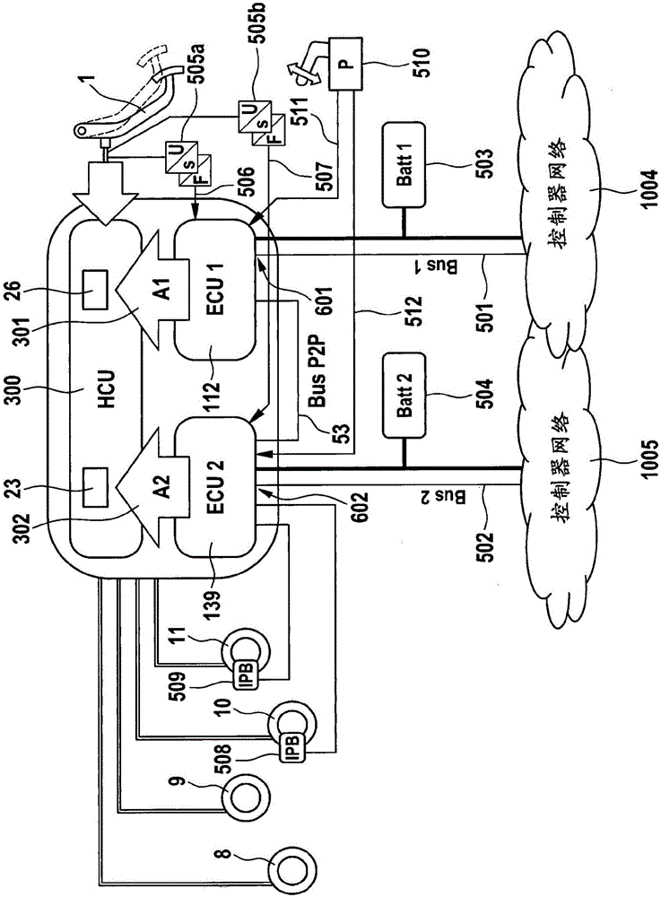
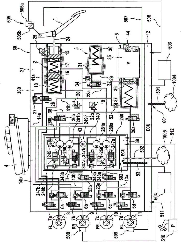
[0045] According to the first embodiment of the present invention figure 1 The braking system shown in has four hydraulically actuatable wheel brakes 8 , 9 , 10 , 11 which are preferably arranged in at least two brake circuits. The driver can initiate braking via the brake pedal. The brake actuation is detected by at least two mutually independent brake actuation sensors 505 a and 505 b , which are each advantageously designed redundantly. According to an example, the brake operation sensors 505a, 505b detect the operation force or operation stroke of the brake pedal 1 .

[0046] The braking system according to the example has a hydraulic control in the form of a hydraulic control unit (HCU) 300, to which is connected an electrically controllable first pressure source (A1) 301 and an electrically controllable second pressure Source (A2) 302 . The pressure sources 301 and 302 can also be part of the hydraulic control unit 300 , ie be integrated in said hydraulic control unit...


PUM


Abstract

The invention relates to a brake system for motor vehicles, which can be controlled both by a driver and independently of the driver in a "brake-by-wire" operating mode, comprising a brake pedal (1), at least two wheel brakes (8, 9, 10, 11) that can be actuated hydraulically, a first and a second brake actuation sensor (505a, 505b), a first electrically controllable pressure source (301, 5), by means of which the wheel brakes can be actuated, a first electronic control unit (112, 12), which is connected to the first brake actuation sensor (505a) and controls the first pressure source (301, 5), a second electrically controllable pressure source (302, 249), by means of which the wheel brakes can be actuated, a second electronic control unit (139, 39), which is connected to the second brake actuation sensor (505b) and controls the second pressure source (302, 249), a hydraulic control device (300), which comprises, in particular, at least a first solenoid valve (26, 26a, 26b) between the wheel brakes and the first pressure source and a second solenoid valve (23, 23a, 23b) between the wheel brakes and the second pressure source, and a data connection (53) between the first electronic control unit (112, 12) and the second electronic control unit (139, 39), wherein the first electronic control unit (112, 12) has a first interface (601) and the second electronic control unit (139, 39) has a second interface (602), wherein the first interface and the second interface are not connected to each other.

Description

technical field [0001] The invention relates to a braking system for a motor vehicle according to the preamble of claim 1 . Background technique [0002] Hydraulic vehicle braking systems are known which are designed as external braking systems and which, in addition to the muscularly actuated brake master cylinder, comprise further electrically controllable pressure and volume supply devices, The wheel brakes are hydraulically connected to the master cylinder and supply the pressure and volume for actuating the wheel brakes, the pressure and volume supply device actuating the wheel brakes in the "brake-by-wire" operating mode. In the event of failure of the electrically controllable pressure and volume supply, the wheel brakes are actuated solely by the muscular force of the vehicle driver. [0003] Thus, for example, an electrohydraulic brake system is known from WO 2011 / 029812 A1, which has a brake master cylinder actuatable by the brake pedal, a stroke simulator and an ...

Claims


Application Information

Patent Timeline
Patent Type & Authority Applications(China)
IPC IPC(8): B60T13/66B60T7/12B60T8/40
CPCB60T7/12B60T8/4072B60T8/409B60T13/66B60T7/22B60T8/321B60T8/4081B60T2270/413B60T7/042B60T8/4266B60T2220/04B60T2270/82
Inventor M·贝西尔S·德鲁姆
Owner CONTINENTAL AUTOMOTIVE TECH GMBH
Why Eureka
Try Eureka