Device for splinter processing and method thereof

A technology of splitting and equipment, applied in nonlinear optics, instruments, optics, etc., can solve the problems of low efficiency and inability to handle the splitting process

Inactive Publication Date: 2017-05-03
SUNRISE A&T CO LTD
View PDF4 Cites 1 Cited by
  • Summary
  • Abstract
  • Description
  • Claims
  • Application Information

AI Technical Summary

Problems solved by technology

[0005] In the conventional technology, there are four methods related to the splitting step: clamping method, knocking method, breaking fragment method and high-flow hot gas method. The clamping method is mainly fixed by the upper and lower clamping blocks, and at the same time Clamp the part to be removed outside the cutting line of the liquid crystal display panel to remove residual materials; the knocking method mainly applies a moderate external force to knock on the part to be removed outside the cutting line of the liquid crystal display panel to remove residual materials , the method of breaking the broken pieces is mainly to apply external force to the panels on both sides of the cutting line through the device, so as to promote the deepening of the cracks on the cutting line, and to separate the effective panel and the residual material; the high-velocity hot gas method is mainly to cut through the impact of high-speed hot gas line, to promote the deepening of the crack of the cutting line, and to separate the effective panel and the residual material. Regarding the above methods, although the splitting effect can be achieved, most of the current splitting methods require the liquid crystal display surface to be processed in a static state, and It is impossible to deal with multiple cutting lines of the LCD panel at the same time, resulting in low efficiency of the process of cracking

Method used


Image

  • Device for splinter processing and method thereof
  • Device for splinter processing and method thereof
  • Device for splinter processing and method thereof

Examples


Embodiment Construction

[0069] In order to make the structural features of the present invention and the achieved effects have a further understanding and recognition, preferred embodiments and detailed descriptions are specially used, which are described as follows:

[0070] Currently, there are many splitting methods for liquid crystal display panels, such as clamping, knocking, breaking and high-velocity hot gas. However, equipment using the above-mentioned splitting process cannot achieve streamlined production. Generally, the equipment for the splitting process requires a short residence time for splitting processing, so it is difficult to meet the existing manufacturing needs of a large number of liquid crystal display panels. and its methods.

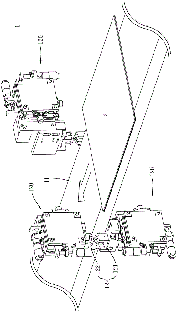
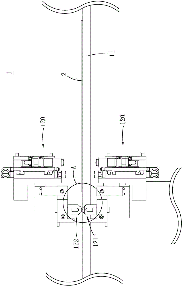
[0071] see figure 1 and figure 2 , which is a schematic diagram and a side view of the splitting process equipment in the first embodiment of the present invention; A split roller set 12, the at least one split roller set 12 is fixed on one side of ...


PUM


Abstract

The invention relates to a device for splinter processing and a method thereof. The device comprises a conveying mechanism and a splinter roller group. The conveying mechanism is used to convey materials. The materials include a body and debris. One side of the material is provided with a cutting line to distinguish the body and debris. The splinter roller group is fixedly arranged on one side of the conveying mechanism. The splinter roller group comprises a lower roller and an upper roller. The upper roller is above the lower roller. The thickness of the material is larger than vertical distance between horizontal height of the lower roller and horizontal height of the upper roller. The side of the material, with the cutting line, is arranged on one side of the conveying mechanism. The conveying mechanism conveys the materials, and through the splinter roller group, a splinter processing is performed. When the material moves continuously, the material is pressed by the lower roller and the upper roller from lower and upper directions at the same time. Thus, the cutting line is split when the material is in a moving state, so as to peel off the debris from the material.

Description

technical field [0001] The present invention relates to a splitting process, in particular to an equipment and method for the splitting process which can be used in streamline production. Background technique [0002] With the development of science and technology, life is getting more and more advanced, and the arrival of the digital age has promoted the vigorous development of high-tech industries. The industrial scale of Liquid Crystal Display (LCD) and the fierce competition among international manufacturers are increasingly To expand, liquid crystal display devices have many advantages such as high image quality, small size, light weight, low driving voltage and low power consumption. Therefore, it is widely used in consumer communication or electronic products such as personal digital assistants (PDAs), mobile phones, video recorders, notebook calculators, desktop displays, car displays, and projection TVs, and has become Mainstream display. [0003] The liquid cryst...

Claims


Application Information

Patent Timeline
Patent Type & Authority Applications(China)
IPC IPC(8): G02F1/1333G02F1/13
CPCG02F1/1303G02F1/133351
Inventor 陈昇阳杨仕帆张继泽
Owner SUNRISE A&T CO LTD
Why Eureka
Try Eureka