Device for Improving Filtration Speed ​​of Cutting Fluid

A technology of filtration speed and filtration device, applied in filtration separation, membrane filter, fixed filter element filter, etc., can solve problems such as accelerated filtration, and achieve the effect of accelerating filtration speed, improving filtration speed and low manufacturing cost

Inactive Publication Date: 2019-01-15
成都欧珀琅精密工具有限公司
View PDF5 Cites 0 Cited by
  • Summary
  • Abstract
  • Description
  • Claims
  • Application Information

AI Technical Summary

Problems solved by technology

Therefore the object of the present invention is to provide the device that improves cutting fluid filtering speed, solves how to accelerate and filter out the problem of solid particle in cutting fluid

Method used


Image

  • Device for Improving Filtration Speed ​​of Cutting Fluid

Examples


Embodiment 1

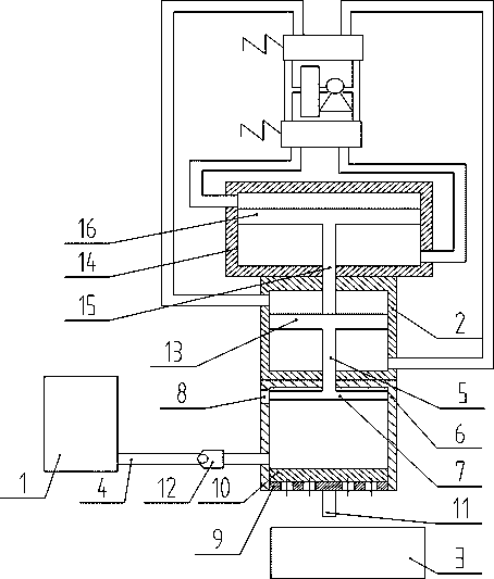
[0021] Such as figure 1 As shown, the device for improving the filtration speed of cutting fluid in the present invention includes a storage tank 1, a first-stage hydraulic cylinder 2, a pressurized hydraulic cylinder 14, a filter device, a liquid storage tank 3 and a pipeline 4; the storage tank 1 is used to store For cutting fluid, the pipeline 4 communicates the storage tank 1 with the filter device; the cutting fluid enters the filter device through the pipeline 4 . The liquid storage tank 3 is located below the filter device, and the liquid storage tank 3 is used to store the liquid filtered by the filter device; the filter device includes a filter assembly and a filter cylinder 6 with a bottom opening, and the filter assembly is arranged on the filter cylinder 6 The bottom; the first stage hydraulic cylinder 2 includes a cylinder body, the first stage piston rod 5 and the piston I13; the booster hydraulic cylinder 14 includes a cylinder body, a booster piston rod 15 and ...

Embodiment 2

[0027] The structure of this embodiment is the same as that of Embodiment 1, and this embodiment is an instruction for the use of Embodiment 1.

[0028] Use the steps of the present invention as follows:

[0029] 1. Supply oil to the lower chamber of the first-stage hydraulic cylinder 2, the piston Ⅰ13 in the first-stage hydraulic cylinder 2 moves upward under the push of oil pressure, and drives the piston Ⅱ7 connected to the first-stage piston rod 5 to move upward , the volume of the inner cavity at the lower end of the piston II7 increases to form a local cavity; at this time, the one-way valve 12 is opened, and the cutting fluid is sucked from the storage tank through the pipeline 4;

[0030] 2. Supply oil to the upper chamber of the first-stage hydraulic cylinder 2, the piston I13 in the first-stage hydraulic cylinder 2 moves downward under the push of oil pressure, and drives the piston II7 connected to the first-stage piston rod 5 to Moving down, the volume of the inne...


PUM


Abstract

The invention discloses a device for increasing the filtering speed of cutting fluid. The device comprises a first-stage hydraulic cylinder, a pressurizing hydraulic cylinder and a filtering device. The filtering device comprises a filtering assembly and a filtering cylinder with an opened bottom. The filtering assembly is arranged at the bottom of the filtering cylinder. The free end of a first-stage piston rod of the first-stage hydraulic cylinder penetrates the top of the filtering cylinder and is located in an inner cavity of the filtering cylinder. A piston II is arranged at the free end of the first-stage piston rod. The size of the cross section of the piston II is matched with the size of the cross section of the inner cavity of the filtering cavity. The inner cavity of the filtering cylinder is divided into an upper sealed cavity body and a lower sealed cavity body through the piston II. The free end of a pressurizing piston rod of the pressurizing hydraulic cylinder penetrates the first-stage hydraulic cylinder and makes contact with a first-stage piston of the first-stage hydraulic cylinder. The arranged pressurizing hydraulic cylinder pushes the first-stage hydraulic cylinder to move downwards and pushes the piston II downwards, and therefore the filtering speed of the cutting fluid is increased, the filtering time of the cutting fluid is shortened, and the time cost is reduced.

Description

technical field [0001] The invention relates to a filtering device, in particular to a device for increasing the filtering speed of cutting fluid. Background technique [0002] Cutting fluid is an industrial liquid used to cool and lubricate cutting tools and workpieces during metal cutting and grinding. The lubricating effect of the cutting fluid during the cutting process can reduce the friction between the rake face and the chip, the flank face and the machined surface, and form a part of the lubricating film, thereby reducing the cutting force, friction and power consumption, and reducing the friction between the tool and the workpiece. The surface temperature of the friction part of the blank and the wear of the tool improve the cutting performance of the workpiece material. During the grinding process, after adding the grinding fluid, the grinding fluid penetrates into the grinding wheel abrasive grain-workpiece and abrasive grain-grinding debris to form a lubricating...

Claims


Application Information

Patent Timeline
Patent Type & Authority Patents(China)
IPC IPC(8): B23Q11/10B01D29/05B01D29/96
CPCB01D29/05B01D29/96B01D2201/202B23Q11/1069
Inventor 钟涛赖永良候晓春
Owner 成都欧珀琅精密工具有限公司
Why Eureka
Try Eureka