
Hybrid brake system bogie and engineering vehicle
A compound braking and bogie technology, which is applied to railway braking systems, operating mechanisms of railway vehicle brakes, railway car body components, etc. Problems such as dynamic and braking deceleration, braking device can not meet the requirements of use, etc., to achieve the effect of improving vertical dynamic performance, compact structure, and large braking force
- Summary
- Abstract
- Description
- Claims
- Application Information
AI Technical Summary
Problems solved by technology
Method used
Image

Examples
Embodiment Construction
[0037] The technical solutions in the embodiments of the present invention will be clearly and completely described below in conjunction with the drawings in the embodiments of the present invention.
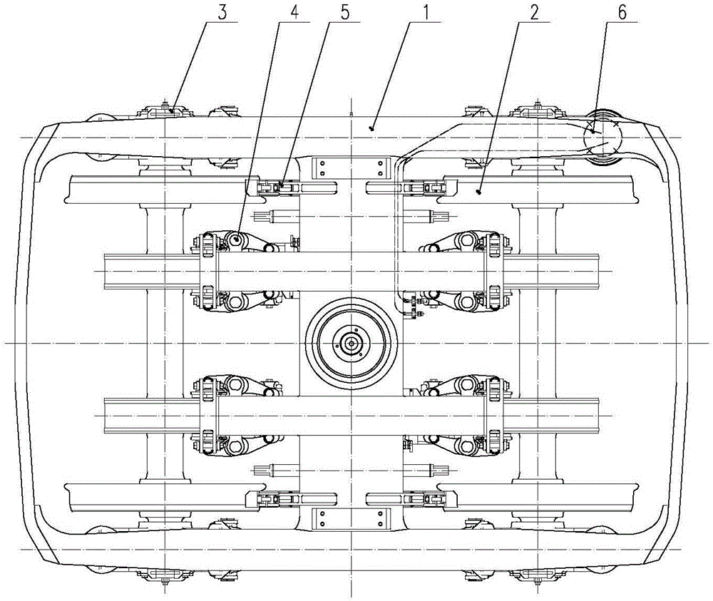
[0038] figure 1 Shown is the structural representation of the present invention.
[0039] The composite brake system bogie of the present invention comprises a frame component 1, a wheel set component 2, an axle box suspension device 3, a disc brake device 4 and a unit brake shoe brake device 5.
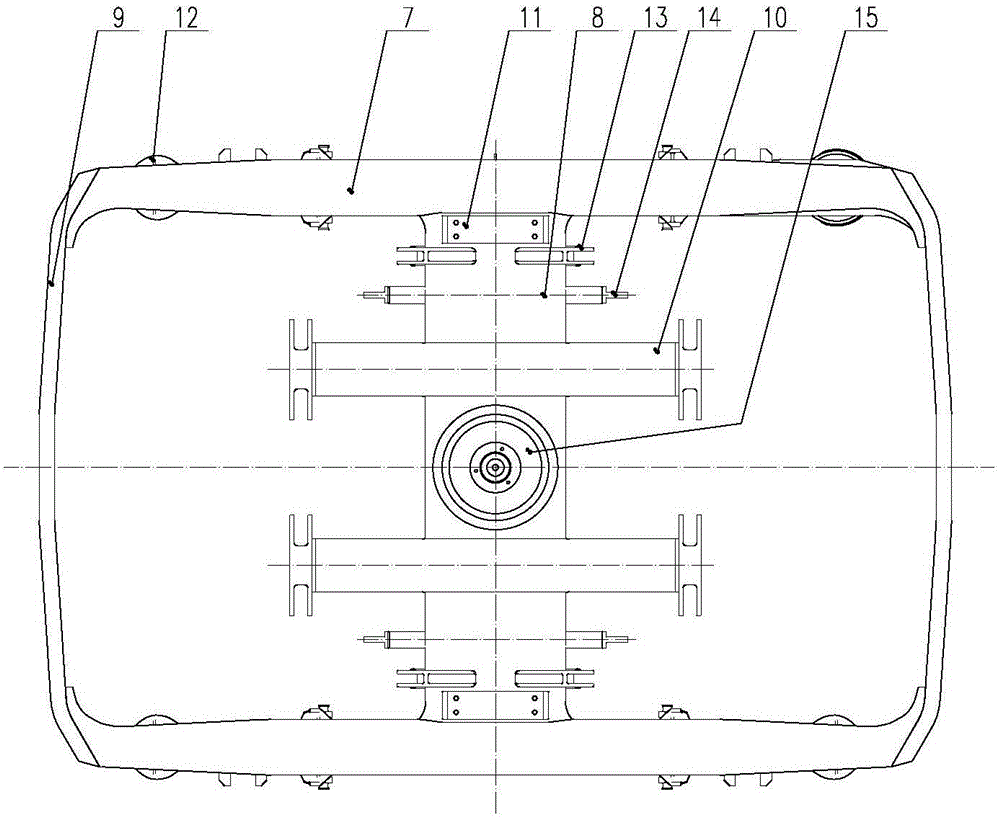
[0040] figure 2 Shown is a structural schematic diagram of the frame composition of the present invention.
[0041] The frame composition 1 is a Japanese-shaped structure composed of side beams 7, cross beams 8 and end beams 9 assembled by welding. The frame has strong rigidity, simple structure and easy maintenance.
[0042] Brake hanger 10 is welded on the crossbeam 8, and brake hanger 10 is connected with disc brake device 4; Elastic side bearing composition 11 is installed on t...
PUM
 Abstract
Description
Claims
Application Information