scan card

A scanning card and image display technology, applied to static indicators, instruments, etc., can solve problems such as limited RGB data sets, difficult TTL signals, and increased product thickness, so as to improve refresh rate and gray scale, improve display effect, and save energy. The effect of development costs

Active Publication Date: 2019-02-26
XIAN NOVASTAR TECH
View PDF5 Cites 0 Cited by
  • Summary
  • Abstract
  • Description
  • Claims
  • Application Information

AI Technical Summary

Problems solved by technology

[0006] However, the FPGA and its supporting related devices in the existing scanning card are relatively large in size, and the HUB board (transfer board) is required to be provided by the screen manufacturer, which increases the thickness of the product and is not conducive to the design of high-density LED display screens.
The limited bandwidth of the scanning card cannot support a large load
Due to its low price, the general-purpose driver chip is still favored by customers even though it has been used for a long time; for the LED box using the general-purpose driver chip, due to its driving characteristics, it is necessary to output grayscale data continuously. However, The RGB data set (display data) output by the FPGA is limited, which cannot meet the occasions where the display effect is relatively high.
In addition, the scanning card and the LED light board module in the LED box are connected by cables. The existing signal transmission and connection methods have the following problems: 1) Each single-ended signal needs to occupy a wire core, resulting in The number of wire cores in the cable is large. Taking a conventional 8-scan LED light board module as an example, if two sets of RGB data are required, plus the clock signal (CLK), latch signal (LAT), and enable signal (OE) , Row selection signal (A, B, C) and other signals have a total of 12 single-ended signals, plus at least one ground signal, at least 13-core cable is required. However, there are often some applications in the LED display industry. The module has a limit on the number of wire cores connected to the cable, and multi-core cable is inconvenient; 2) Due to the large number of cable cores, there are many contact points between the cable and the connector of the LED light board module , A single wire core failure or poor contact will lead to abnormal display. The faults caused by this reason account for a large proportion of LED display application faults; 3) TTL signals have limited transmission distance due to signal attenuation, usually no more than 2 meters, some The application requires a longer transmission distance, so TTL signals are not competent; and 4) the transmission of TTL signals by cables leads to greater signal radiation, which makes it difficult for LED displays to pass EMC tests

Method used


Image

  • scan card
  • scan card
  • scan card

Examples


Embodiment Construction

[0025] In order to make the above objects, features and advantages of the present invention more comprehensible, specific implementations of the present invention will be described in detail below in conjunction with the accompanying drawings.

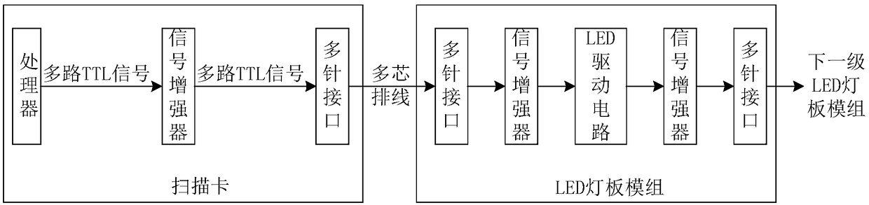
[0026] Specifically, the following embodiments of the present invention propose a new scanning card technical solution, which makes the functions of the scanning card chip as much as possible, in order to solve the problems in the existing LED display control system, reduce the volume of the scanning card, and support large-band It supports high-density and small-pitch screens; at the same time, it solves the problem of poor display effect of the existing scanning card in the general-purpose driver chip screen, and improves the display effect of the LED display; The number of wire cores improves the stability and reliability of transmission, reduces EMI, and meets EMC requirements more easily.

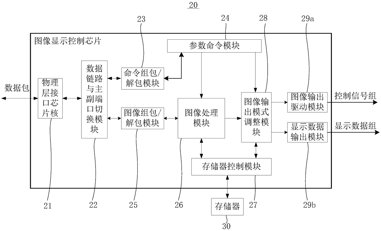
[0027] see figure 2 , which is a schem...


PUM


Abstract

The present invention provides a scanning card (40) suitable for the connection with a LED lamp board module. The scanning card (40) comprises: a circuit board (41) and an input / output circuit and an image display control chip (20) arranged on the circuit board (41). The image display control chip (20) is connected with the input / output circuit and is configured to receive a command pack and an image data pack through the input / output circuit and perform cut-out, correction, rearrangement and gray level extraction of the obtained image data through unpacking the image data pack according to the parameter data obtained by unpacking the command pack to output a control signal set and a display data set to the LED lamp board module for image display, wherein the image display control chip (20) is preferably an ASIC chip. The scanning card can perform chip modularization to the greatest extent so as to reduce the size of the scanning card and improve the display effect of the LED display screen body.

Description

technical field [0001] The invention relates to the field of display technology, in particular to components in an LED display screen control system. Background technique [0002] The existing LED display control system mainly includes a sending card, a scanning card and an LED display, wherein the scanning card is arranged in each LED cabinet, and multiple LED cabinets are spliced ​​to form an LED display. The display effect of the LED display is directly determined by the scanning card (or LED display control board, receiving card) configured in each LED cabinet. When the specifications of the LED box are determined, the performance parameters of the LED display are basically determined, especially in the general-purpose driver chip LED display. [0003] With the development of small spacing, the number of pixels loaded on the scanning card needs to increase, and the limited bandwidth of the scanning card makes it impossible to display the image under a large bandwidth; ...

Claims


Application Information

Patent Timeline
Patent Type & Authority Patents(China)
IPC IPC(8): G09G3/32
CPCG09G3/32
Inventor 王伙荣刘德福
Owner XIAN NOVASTAR TECH
Why Eureka
Try Eureka