
Charger circuit capable of automatically identifying positive electrode and negative electrode
An automatic identification, positive and negative technology, applied in the direction of battery disconnection circuit, battery circuit device, current collector, etc., can solve the problems of different battery charger styles and use objects, limited charging times, and battery chargers that cannot be satisfied.
- Summary
- Abstract
- Description
- Claims
- Application Information
AI Technical Summary
Problems solved by technology
Method used
Image

Examples
Embodiment Construction
[0008] The present invention will be further described below in conjunction with the accompanying drawings and specific embodiments.
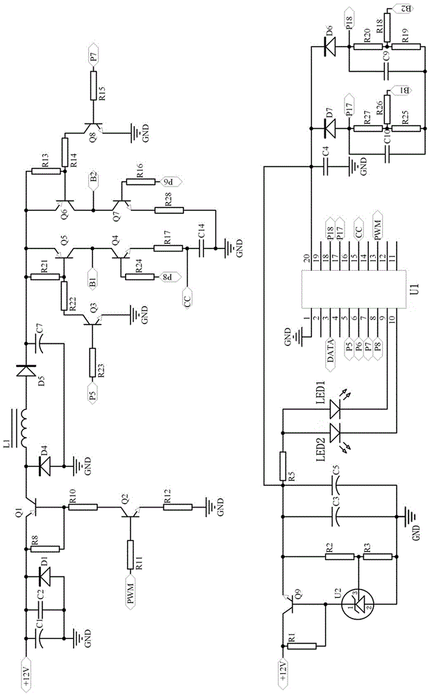
[0009] See figure 1, automatic identification of positive and negative charger circuit, including IC control circuit, light emitting diode control circuit connected to IC control circuit, IC power supply circuit and output control circuit and automatic duty cycle adjustment circuit, said light emitting diode control circuit and IC power supply The circuits are connected to each other, and the output control circuit and the automatic adjustment duty cycle circuit are connected to each other; the IC control circuit includes the first chip U1, the sixth diode D6, the seventh diode D7, the fourth capacitor C4, the first Nine capacitors C9, tenth capacitors C10, eighteenth resistors R18, nineteenth resistors R19, twentieth resistors R20, twenty-fifth resistors R25, twenty-sixth resistors R26 and twenty-seventh resistors R27, the The first chip U1 i...
PUM
 Abstract
Description
Claims
Application Information