Push type self-aligning hydraulic release bearing wheel cylinder unit
What is Al technical title?
Al technical title is built by PatSnap Al team. It summarizes the technical point description of the patent document.
A release bearing and self-aligning technology, applied in clutches, fluid-driven clutches, non-mechanical-driven clutches, etc., can solve the problems of increased separation stroke and incomplete separation, achieve small torque loss, simple and reliable installation, and improve performance. Effect
Active Publication Date: 2014-06-18
NANJING BEARING
View PDF8 Cites 0 Cited by
Summary
Abstract
Description
Claims
Application Information
AI Technical Summary
This helps you quickly interpret patents by identifying the three key elements:
Problems solved by technology
Method used
Benefits of technology
Problems solved by technology
With the intensification of wear, the separation stroke increases, resulting in defects such as incomplete separation
Method used
Image
Click on the blue label to locate the original text in one second.
Reading with bidirectional positioning of images and text.
Examples
Embodiment Construction
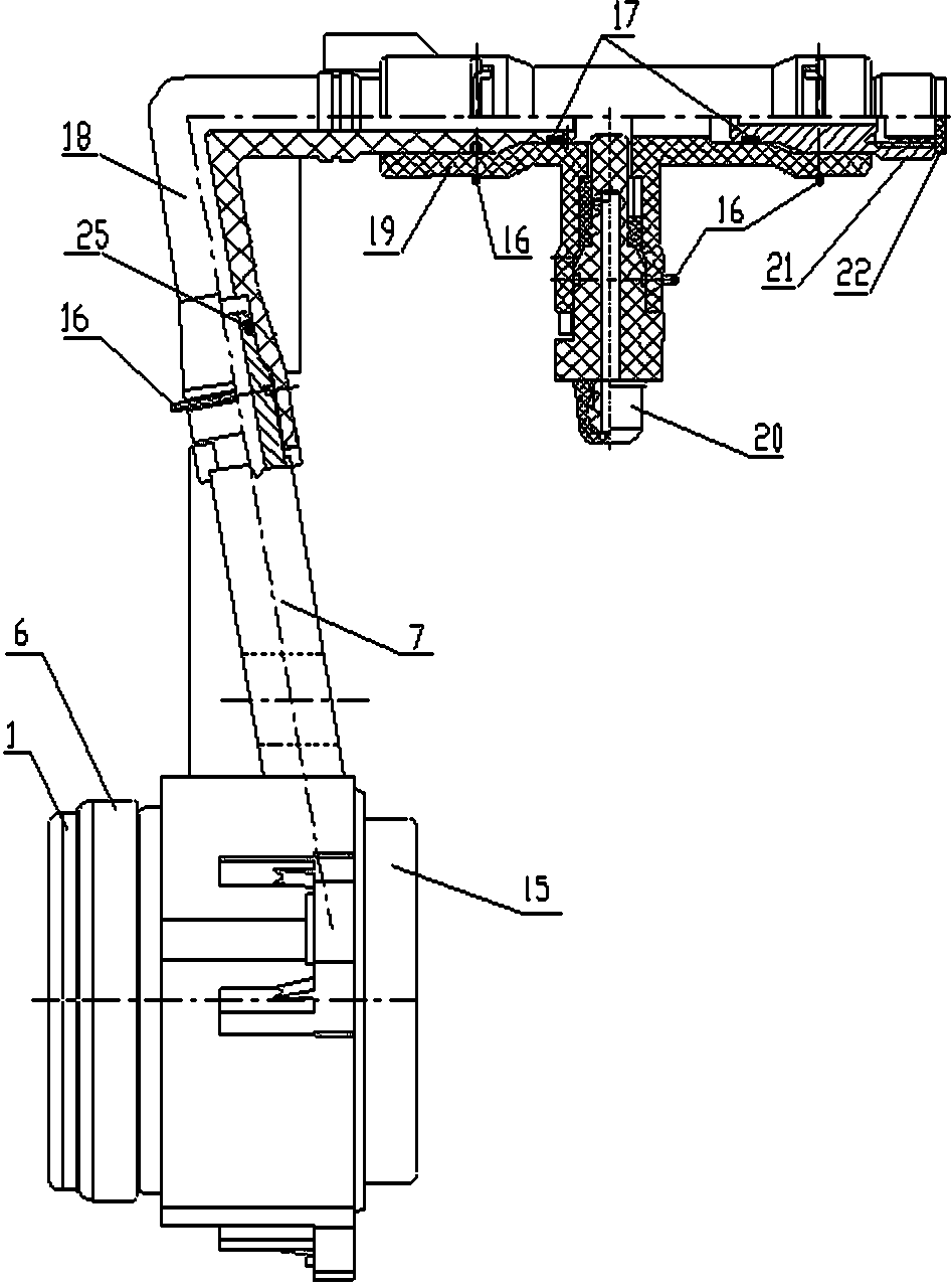
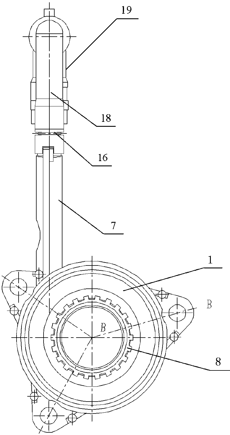
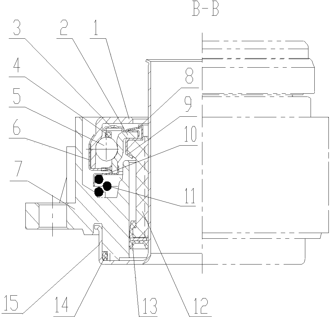
[0022] Refer to attached Figure 1~3 The push-type self-aligning hydraulic release bearing sub-pump unit includes self-aligning bearing mechanism, hydraulic sub-pump mechanism and air release device; the self-aligning bearing mechanism consists of outer ring 1, inner ring 2, cage 4, steel ball 5, The inner dust cover 3, the outer cover 6, the self-aligning spring piece 8, the sleeve 12 and the sleeve seat 9 are composed. The bearing of the self-aligning bearing mechanism adopts an angular contact design, and the centering function is realized by the self-aligning spring piece 8. The centering force That is, the force required for the radial displacement of the self-aligning spring sheet 8 after being compressed is determined by the positive pressure generated by the compressed self-aligning spring sheet 8 .
[0023] The hydraulic sub-pump mechanism is composed of a cylinder block 7, a mandrel 15, an apron 13, a mandrel sealing ring 14, a return spring 11 and a spring seat 10. ...
PUM
Abstract
The invention discloses a push type self-aligning hydraulic release bearing wheel cylinder unit, relating to a vehicular release bearing unit. The push type self-aligning hydraulic release bearing wheel cylinder unit is especially suitable for passenger cars and commercial vehicles using push type clutches, in particular cars using the push type clutches and belongs to the technical field of automobile bearings. The push type self-aligning hydraulic release bearing wheel cylinder unit comprises a self-aligning bearing mechanism, a hydraulic wheel cylinder mechanism and an air bleeder, wherein the self-aligning bearing mechanism consists of an outer ring, an inner ring, a retainer, a steel ball, an inner dustproof cover, an outer cover, an aligning leaf spring, a sleeve and a sleeve seat; the hydraulic wheel cylinder mechanism consists of a cylinder body, a mandrel, a leather ring, a mandrel sealing ring, a return spring and a spring seat; and the air bleeder comprises an oil feeding connector, a clamp, a first O-shaped ring, a second O-shaped ring, an exhaust valve tee joint, an air bleed screw sealing ring, an air bleed screw, an air bleed screw cap, an air feeding connector screw and a choke plug. The push type self-aligning hydraulic release bearing wheel cylinder unit disclosed by the invention has the use function of the release bearing and the function of the wheel cylinder and is hydraulically driven. The push type self-aligning hydraulic release bearing wheel cylinder unit has the advantages of higher service efficiency, longer service life and higher flexibility in operation.
Description
technical field [0001] The push-type self-aligning hydraulic release bearing sub-pump unit of the present invention relates to a release bearing unit for vehicles, which is especially suitable for passenger cars and commercial vehicles using push clutches, especially cars using push clutches, and belongs to Automotive bearing technology field. Background technique [0002] The working principle of the traditional automobile clutch is divided into two types, one is the mechanical pull bar mechanism: step on the clutch pedal, pull the shift fork through the pull bar, the shift fork pushes or pulls the release bearing to separate the active and passive friction plates of the clutch, cut off The power output of the engine, so as to realize the clutch function. The other is a hydraulic transmission mechanism: step on the clutch pedal, the power is transmitted to the clutch master cylinder, the master cylinder outputs oil pressure to the slave cylinder, the slave cylinder pushes ...
Claims
Application Information
Patent Timeline
Application Date:The date an application was filed.
Publication Date:The date a patent or application was officially published.
First Publication Date:The earliest publication date of a patent with the same application number.
Issue Date:Publication date of the patent grant document.
PCT Entry Date:The Entry date of PCT National Phase.
Estimated Expiry Date:The statutory expiry date of a patent right according to the Patent Law, and it is the longest term of protection that the patent right can achieve without the termination of the patent right due to other reasons(Term extension factor has been taken into account ).
Invalid Date:Actual expiry date is based on effective date or publication date of legal transaction data of invalid patent.