Low-noise optical probes for reducing ambient noise
a technology of ambient noise and optical probes, which is applied in the field of low-noise, disposable and reusable optical probes, can solve the problems of grossly corrupting the measured signal, difficult to interpret the measured signal, and erratic finger compression
- Summary
- Abstract
- Description
- Claims
- Application Information
AI Technical Summary
Benefits of technology
Problems solved by technology
Method used
Image
Examples
first embodiment
[0174]FIG. 30 is a flow chart which illustrates the general steps in accordance with the present invention to manufacture the disposable, optical probe 2002 depicted in FIGS. 29A-29C. A flex circuit is formed on a flex circuit panel as represented by an activity block 3005. In one advantageous embodiment, the flex circuit panel comprises a copper / MYLAR™ or copper / CAPTON™ laminant, or, alternatively, is formed by depositing a conductive ink on MYLAR™. For example, FIG. 31 depicts three etched flex circuits on a flexible circuit panel material. The flex circuits have been formed by etching in one preferred embodiment, and are comprised of one-ounce copper (approximately 1.3 mils) over 1 mil of MYLAR™ or CAPTON™.
[0175]After the flex circuit has been etched in an appropriate copper coated MYLAR™ substrate material, conductive pressure sensitive adhesive (PSA) 2102 is applied to the end of the flex circuits where the detector will be placed (hereinafter, the “detector end”), as depicted ...
second embodiment
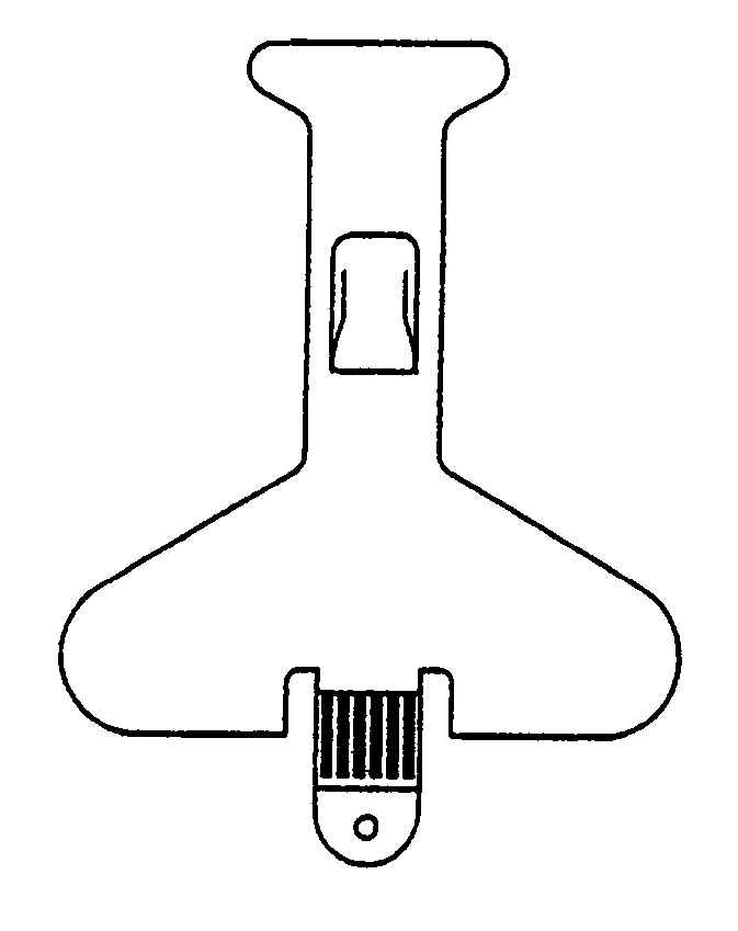
[0201]Another embodiment of a low noise optical probe 2200 is depicted in FIG. 40A. This embodiment is advantageous for use with neonates, as will be further described below. FIG. 41 is a flow chart which details the general method used for manufacturing a neonatal disposable optical probe 2200 in accordance with this second embodiment of the present invention.
[0202]As with the previous embodiment, the neonatal probe 2200 is constructed of several layers. A first tape layer 2210 is laid out as represented in an activity block 4010, and depicted in FIG. 42. Advantageously, the first tape layer 2210 is constructed from release liner material. The first tape layer 2210 has adhesive portions on one side for adhesion to the tissue material under test, as will be further understood below. In the present embodiment, the release liner is a conventional paper type release liner for the medical industry.
[0203]In a preferred embodiment, the first tape layer 2210 has a first portion of adhesive...
embodiment 2500
[0223]Another embodiment of the method of making the neonatal probe is illustrated in FIGS. 51-55. An X-ray type view of the alternative embodiment 2500 is depicted in FIG. 51. As illustrated in FIG. 51, the probe 2500 has a detector 2502, an emitter 2504, a flex circuit 2506, a low noise cavity 2508 and a cover 2510 for the optical cavity 2508, top and base tapes 2512, 2514, an identification resistor 2516, thru connections 2518, 2520, and a connection tab 2522. This embodiment of the probe is depicted without the tape extension, such as the extension 2400 (FIG. 48), but could include a tape extension in one embodiment. The overall configuration of the finished probe 2500 is nearly identical to the probe of FIG. 49. However, the shielding is different, the optical cavity has a cover, and the probe 2500 is constructed using two tapes instead of four. The construction of this embodiment of the probe 2500 is similar to the adult probe from the standpoint of the tape-up.
[0224]FIGS. 52A...
PUM
| Property | Measurement | Unit |
|---|---|---|
| depth | aaaaa | aaaaa |
| depth | aaaaa | aaaaa |
| depth | aaaaa | aaaaa |
Abstract
Description
Claims
Application Information
 - R&D
- Intellectual Property
- Life Sciences
- Materials
- Tech Scout
- Unparalleled Data Quality
- Higher Quality Content
- 60% Fewer Hallucinations
Browse by: Latest US Patents, China's latest patents, Technical Efficacy Thesaurus, Application Domain, Technology Topic, Popular Technical Reports.
© 2025 PatSnap. All rights reserved.Legal|Privacy policy|Modern Slavery Act Transparency Statement|Sitemap|About US| Contact US: help@patsnap.com


