
Low-noise optical probes for reducing ambient noise

a technology of ambient noise and optical probes, which is applied in the field of low-noise, disposable and reusable optical probes, can solve the problems of grossly corrupting the measured signal, difficult to interpret the measured signal, and erratic finger compression

Inactive Publication Date: 2009-06-04
JPMORGAN CHASE BANK NA
View PDF102 Cites 10 Cited by
  • Summary
  • Abstract
  • Description
  • Claims
  • Application Information

AI Technical Summary

Benefits of technology

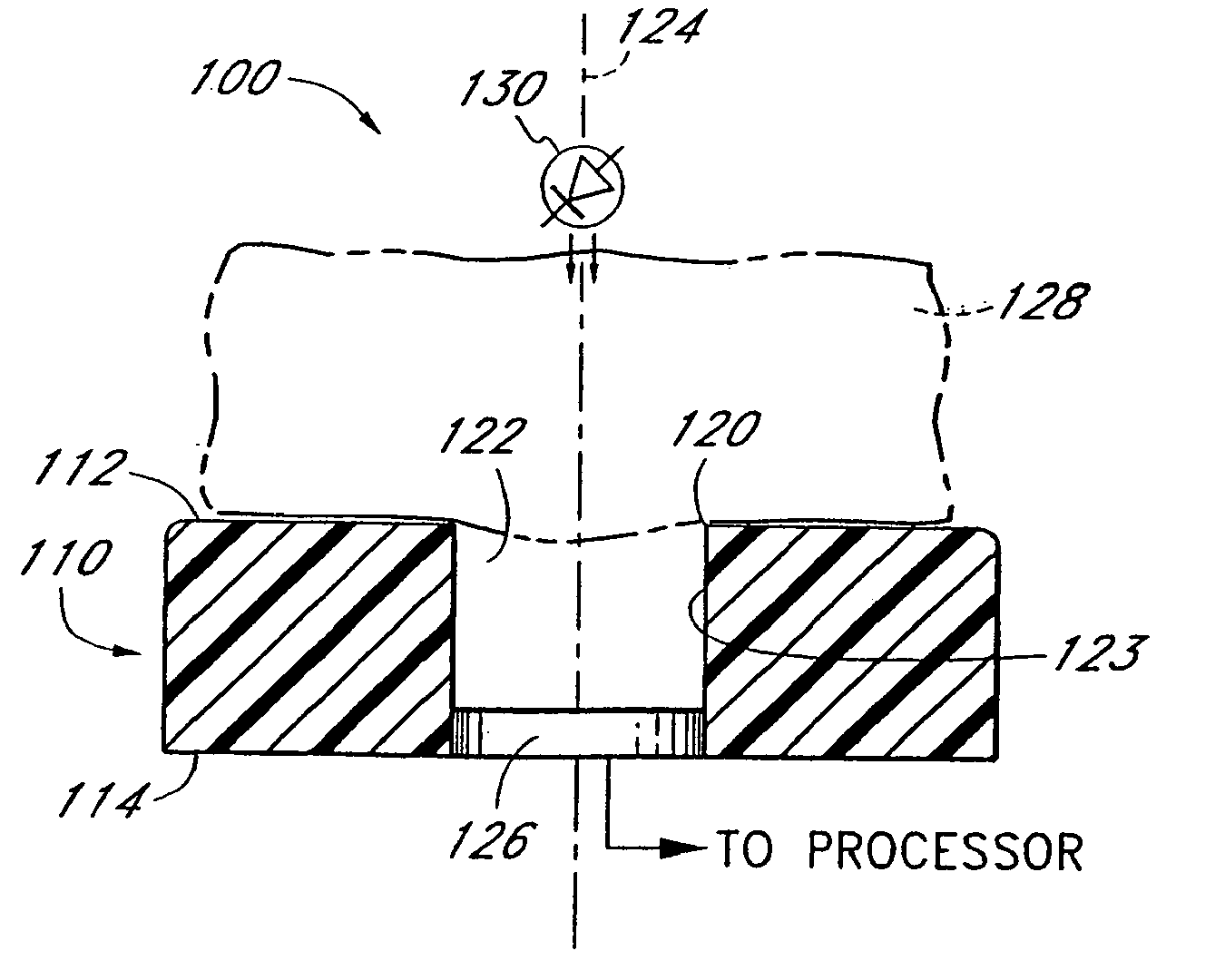
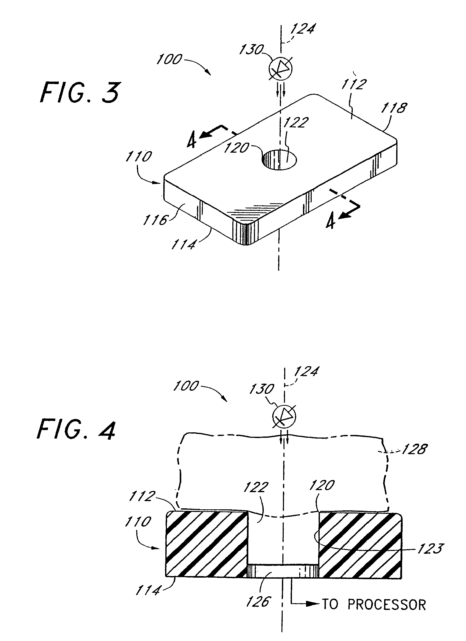
The probe effectively reduces motion-induced noise and stabilizes the optical path length, resulting in a clearer and more interpretable signal for determining medium characteristics, even under adverse conditions such as patient movement.

Problems solved by technology

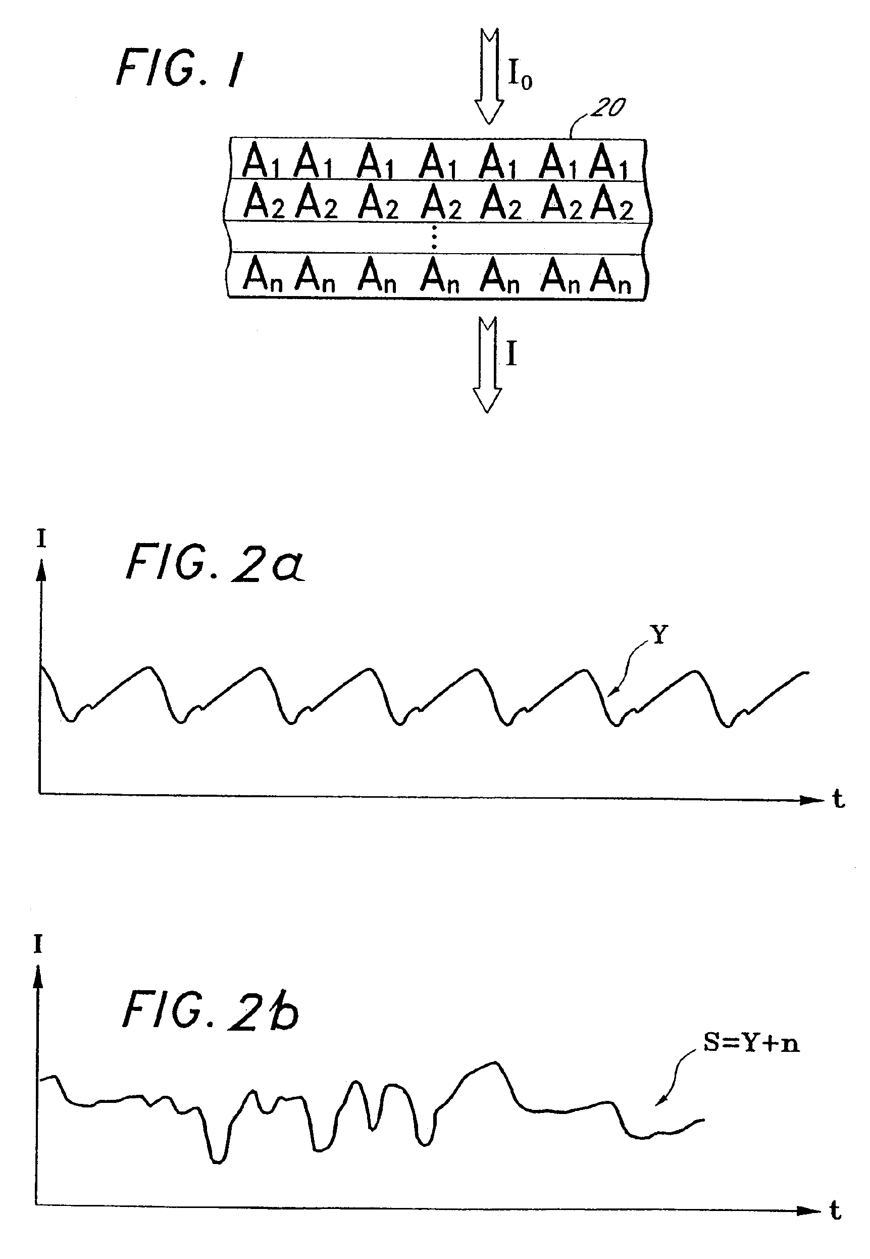
Since a patient generally moves in an erratic fashion, the compression of the finger is erratic.
This causes the change in optical path length to be erratic, making the absorption erratic, resulting in a difficult to interpret measured signal.
Many prior art optical probes are designed for use only when a patient is relatively motionless since, as discussed above, motion induced noise can grossly corrupt the measured signal.
However, this optimization forces compressible portions of the patient's body to be in contact with surfaces which compress these portions of the patient's body when the patient moves.
This can cause extreme changes in the thickness of material through which optical energy passes, i.e., changes in the optical path length and changes due to scattering as a result of venous blood movement during motion.
Changes in the optical path length can produce enough distortion in the measured signal to make it difficult or impossible to determine desired information.
Many difficulties relating to motion-induced noise have been encountered in providing such an optical probe inexpensively.
Furthermore, such probes tend to be difficult to use in certain applications, such as, applications where a patient's finger may move or shift during measurement, or, in a more extreme case, when the optical probe is employed on small children who typically do not sit still during the measurement process.

Method used


Image

  • Low-noise optical probes for reducing ambient noise
  • Low-noise optical probes for reducing ambient noise
  • Low-noise optical probes for reducing ambient noise

Examples


first embodiment

[0173]FIG. 30 is a flow chart which illustrates the general steps in accordance with the present invention to manufacture the disposable, optical probe 2002 depicted in FIGS. 29A-29C. A flex circuit is formed on a flex circuit panel as represented by an activity block 3005. In one advantageous embodiment, the flex circuit panel comprises a copper / MYLAR™ or copper / CAPTON™ laminant, or, alternatively, is formed by depositing a conductive ink on MYLAR™. For example, FIG. 31 depicts three etched flex circuits on a flexible circuit panel material. The flex circuits have been formed by etching in one preferred embodiment, and are comprised of one-ounce copper (approximately 1.3 mils) over 1 mil of MYLAR™ or CAPTON™.

[0174]After the flex circuit has been etched in an appropriate copper coated MYLAR™ substrate material, conductive pressure sensitive adhesive (PSA) 2102 is applied to the end of the flex circuits where the detector will be placed (hereinafter, the “detector end”), as depicted ...

second embodiment

[0200]Another embodiment of a low noise optical probe 2200 is depicted in FIG. 40A. This embodiment is advantageous for use with neonates, as will be further described below. FIG. 41 is a flow chart which details the general method used for manufacturing a neonatal disposable optical probe 2200 in accordance with this second embodiment of the present invention.

[0201]As with the previous embodiment, the neonatal probe 2200 is constructed of several layers. A first tape layer 2210 is laid out as represented in an activity block 4010, and depicted in FIG. 42. Advantageously, the first tape layer 2210 is constructed from release liner material. The first tape layer 2210 has adhesive portions on one side for adhesion to the tissue material under test, as will be further understood below. In the present embodiment, the release liner is a conventional paper type release liner for the medical industry.

[0202]In a preferred embodiment, the first tape layer 2210 has a first portion of adhesive...

embodiment 2500

[0222]Another embodiment of the method of making the neonatal probe is illustrated in FIGS. 51-55. An X-ray type view of the alternative embodiment 2500 is depicted in FIG. 51. As illustrated in FIG. 51, the probe 2500 has a detector 2502, an emitter 2504, a flex circuit 2506, a low noise cavity 2508 and a cover 2510 for the optical cavity 2508, top and base tapes 2512, 2514, an identification resistor 2516, thru connections 2518, 2520, and a connection tab 2522. This embodiment of the probe is depicted without the tape extension, such as the extension 2400 (FIG. 48), but could include a tape extension in one embodiment. The overall configuration of the finished probe 2500 is nearly identical to the probe of FIG. 49. However, the shielding is different, the optical cavity has a cover, and the probe 2500 is constructed using two tapes instead of four. The construction of this embodiment of the probe 2500 is similar to the adult probe from the standpoint of the tape-up.

[0223]FIGS. 52A...


PUM


Abstract

An optical probe, which is particularly suited to reduce noise in measurements taken on an easily compressible material, such as a finger, a toe, a forehead, an earlobe, or a lip, measures characteristics of the material. A neonatal and adult disposable embodiment of the probe include adhesive coated surfaces to securely affix the probe onto the patient. In addition, the surface of the probe is specially constructed to reduce the effect of ambient noise.

Description

REFERENCE TO RELATED APPLICATIONS[0001]The present application claims priority benefit under 35 U.S.C. § 120 to, and is a continuation U.S. patent application Ser. No. 10 / 957,843, filed Oct. 4, 2004 entitled “Low-Noise Optical Probes for Reducing Ambient Noise,” now U.S. Pat. No. 7,483,730, which is a continuation of U.S. patent application Ser. No. 10 / 260,049, filed Sep. 27, 2002 entitled “Low-Noise Optical Probes for Reducing Ambient Noise,” now U.S. Pat. No. 6,813,511, which is a continuation of U.S. patent application Ser. No. 09 / 898,990, filed Jul. 3, 2001 entitled “Low-Noise Optical Probes for Reducing Light Piping,” now U.S. Pat. No. 6,792,300, which is a continuation of U.S. patent application Ser. No. 09 / 094,202, filed Jun. 9, 1998 entitled “Low-Noise Optical Probes,” now U.S. Pat. No. 6,256,523, which is a continuation of U.S. patent application Ser. No. 08 / 543,789, filed Oct. 16, 1995 entitled “Low Noise Optical Probes,” now U.S. Pat. No. 5,782,757, which is a continuatio...

Claims


Application Information

Patent Timeline
Patent Type & Authority Applications(United States)
IPC IPC(8): A61B5/1455A61B5/022A61B5/00A61B5/024A61B5/0245A61B5/145G01N21/17G01N21/59H05K1/18
CPCH05K1/189A61B5/6829Y10T29/49826A61B5/6826A61B2562/08A61B2562/12A61B5/6838A61B5/02427A61B5/14552
Inventor DIAB, MOHAMEDKIANI-AZARBAYJANY, ESMAIELTOBLER, DAVID R.GERHARDT, THOMAS J.MASON, EUGENE E.MILLS, MIKE A.
Owner JPMORGAN CHASE BANK NA
Learn More