Electric wheeled apparatus

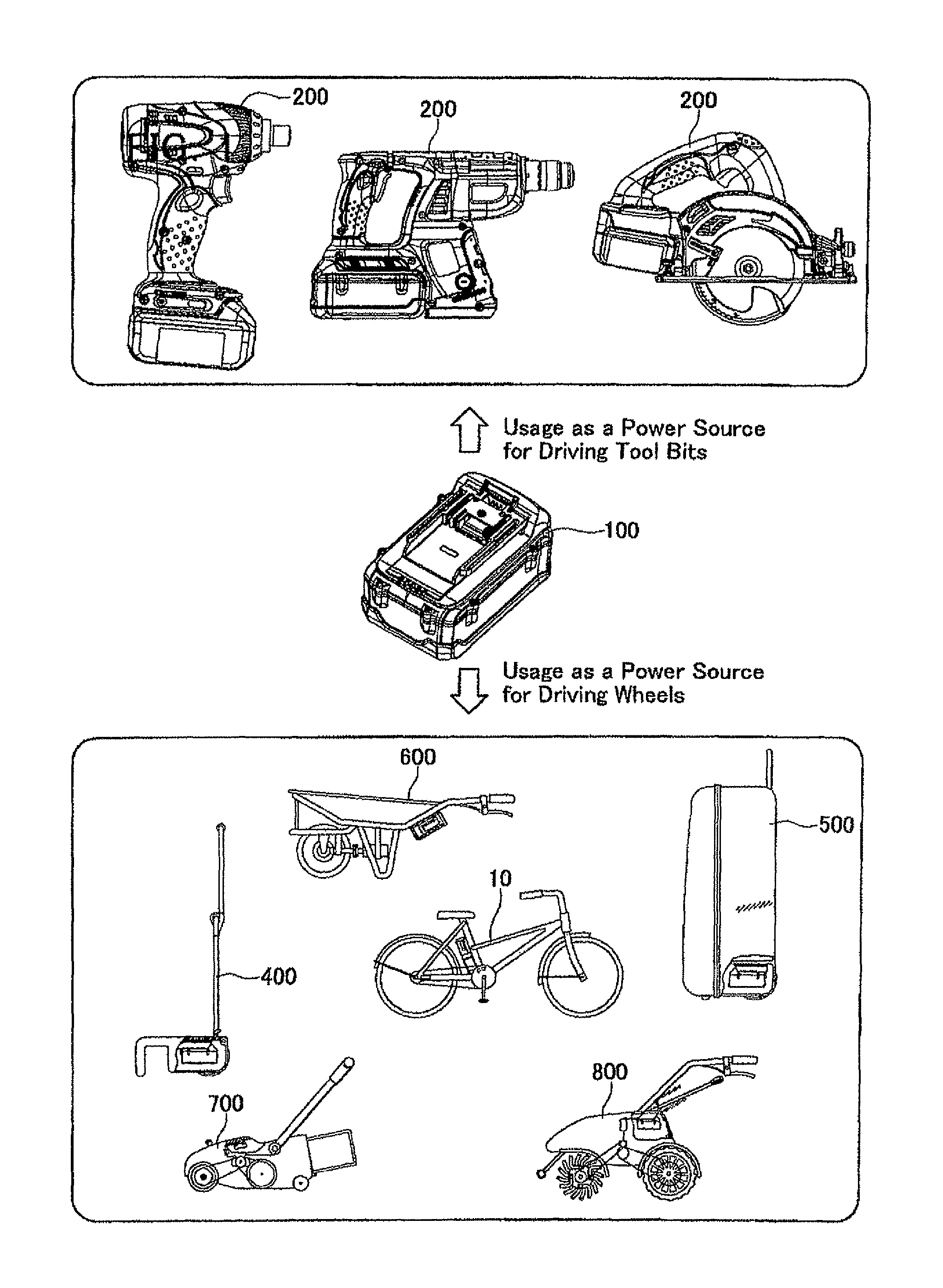
a technology of electric wheels and electric power tools, which is applied in the direction of electric/hybrid propulsion, wheelchairs/patient conveyances, electric devices, etc., can solve the problems of low frequency with which each battery pack is used, the inability to use batteries of other products for a long time, and the inability to use electric power tools for a long period of time, etc., to achieve excellent reliability, high output voltage, and large recharging capacity

Active Publication Date: 2014-10-07
MAKITA CORP
View PDF40 Cites 811 Cited by
  • Summary
  • Abstract
  • Description
  • Claims
  • Application Information

AI Technical Summary

Benefits of technology

[0006]First, compared to battery packs for other portable devices, the battery packs used in electric power tools have a high output voltage and a large recharging capacity, and is sufficient for use as the power source in an electric wheeled apparatus. In addition, because there are many battery packs for electric power tools that are used in harsh conditions (such as outdoors, etc.), many superior technologies have been developed and employed therein, and the reliability of these products is excellent (i.e., they rarely break down).
[0007]Second, there are many users of electric power tools that own a plurality of battery packs for one electric power tool, so that the electric power tool can be used for a long period of time. However, because there is only a small chance that the electric power tool in fact is used for a long period of time, a frequency with which each battery pack is used is low, and as a practical matter, the battery packs that one owns are not made good use thereof. In this case, the battery packs for use in the electric power tools that the user owns can be effectively used if they can also be used in the electric wheeled apparatus. For example, the user who uses an electric power tool at work can use the battery pack for the electric power tool in the electric wheeled apparatus during leisure time.
[0008]Third, there are many electric power tools that are used in a variety of manufacturing plants and construction sites. The workers in the manufacturing plants and construction sites will sometime carry the electric power tools, as well as travel around work sites by the electric wheeled apparatuses. In this case, there hardly is any case that the workers use the electric wheeled apparatuses and the electric power tools at the same time. In other words, the electric power tool is rarely used while travelling on the electric wheeled apparatus, and the electric wheeled apparatus is rarely used while working with the electric power tool. Thus, if the electric wheeled apparatus can use the battery pack for the electric power tool, the battery pack can be used in the electric wheeled apparatus while the electric wheeled apparatus is being used, and the battery pack can be used in the electric power tool when work is being performed with the electric power tool. The battery pack can be effectively used, and also a number of battery packs that must be transported to the work site can be reduced. Alternatively, it is also possible that only the electric power tool is transported to the work site by an electric unmanned carrier, without any worker traveling on the electric unmanned carrier. Even in this case, by using the battery pack on the unmanned carrier when transporting the electric power tool, and using the same battery pack in the electric power tool at the work site, the battery pack for the electric power tool can be effectively used.
[0010]The electric wheeled apparatus can use the battery pack of the electric power tool as a power source, and a dedicated battery pack and charger are not necessary. The user of the electric power tool can also make good use of the battery pack for the electric power tool that the user owns in the electric wheeled apparatus. Because the battery pack is used frequently, it will not be wasteful to own multiple battery packs, and by owning multiple battery packs, it will become possible to use the electric power tool for a long period of time when needed.

Problems solved by technology

With these types of electric wheeled apparatuses, a dedicated battery pack is used for each product, and the battery packs of other products cannot be used.
Second, there are many users of electric power tools that own a plurality of battery packs for one electric power tool, so that the electric power tool can be used for a long period of time.
However, because there is only a small chance that the electric power tool in fact is used for a long period of time, a frequency with which each battery pack is used is low, and as a practical matter, the battery packs that one owns are not made good use thereof.

Method used


Image

  • Electric wheeled apparatus
  • Electric wheeled apparatus
  • Electric wheeled apparatus

Examples


embodiment 1

(Embodiment 1)

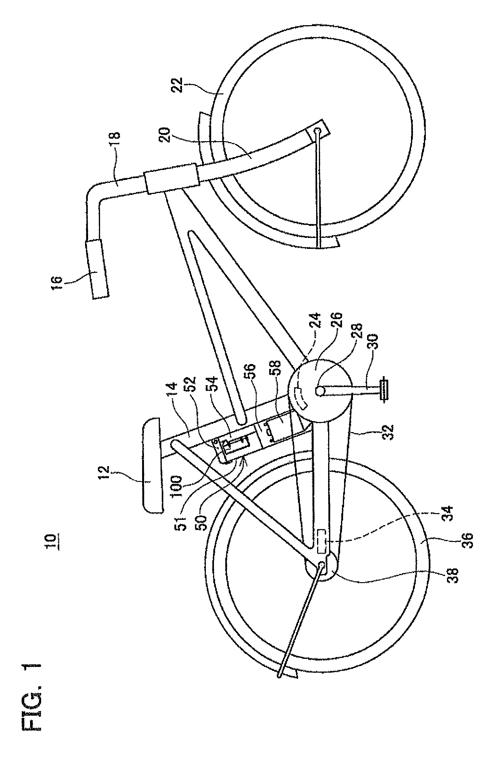
[0056]An electric bicycle 10 of Embodiment 1 will be described with reference to the drawings. The electric bicycle 10 is an example of an electric bicycle in which the present teachings have been realized. As shown in FIG. 1, the electric bicycle 10 has a front wheel 22 and a rear wheel 36 rotatably provided on a main body 14. The main body 14 has a stem 18 that is pivotable. The stem 18 includes a fork 20 that rotatably supports the front wheel 22, and a handle 16 that is grasped by a user. Brake levers (not illustrated in the drawings) are provided on both ends of the handle 16.

[0057]The electric bicycle 10 has a saddle 12 on which a user sits, and crank pedals 30 on which the user applies pedal force. The crank pedals 30 have a shaft 28 that is rotatably supported by the main body 14.

[0058]The electric bicycle 10 comprises a drive sprocket 26 that is concentrically fixed on the central shaft 28 of the crank pedals 30, a driven sprocket 38 that is concentrically fix...

embodiment 2

(Embodiment 2)

[0071]An electric bicycle of Embodiment 2 will be described. The electric bicycle of Embodiment 2 is the electric bicycle 10 of Embodiment 1, in which the battery interface 54 and supply circuit 72 have been changed. Because the configuration of the other aspects of the electric bicycle of Embodiment 2 has not been particularly changed, duplicate description will be omitted by applying the same reference numbers.

[0072]As shown in FIG. 10, the electric bicycle 10 of Embodiment 2 is provided with three pack receiving portions 60a, 60b, 60c in the battery interface 54, and removably receive a maximum of three battery packs 100a, 100b, 100c (hereinafter sometimes abbreviated as battery packs 100). Similar to Embodiment 1, each pack receiving portion 60a, 60b, 60c is provided with a pair of ribs 62a, 62b, 62c and a connection plug 64a, 64b, 64c. Each connection plug 64a, 64b, 64c comprises a positive terminal connection terminal 66a, 66b, 66c, a negative terminal connection...

embodiment 3

(Embodiment 3)

[0081]An electric bicycle of Embodiment 3 will be described. The electric bicycle of Embodiment 3 is the electric bicycle 10 of Embodiment 2, in which primarily the supply circuit 72 has been changed. Because the configuration of the other aspects of the electric bicycle of Embodiment 2 have not been particularly changed, duplicate description will be omitted by applying the same reference numbers.

[0082]As shown in FIG. 15, the supply circuit 72 of Embodiment 3 can connect the three attached battery packs 100a, 100b, 100c in series with the electric motor 58. In other words, with the supply circuit 72 of Embodiment 3, the negative terminal connection terminal 68a of the first connection plug 64a is connected to the positive terminal connection terminal 66b of the second connection plug 64b via a first connection line 82a, and the negative terminal connection terminal 68b of the second connection plug 64b is connected to the positive terminal connection terminal 66c of ...


PUM


Abstract

An electric wheeled apparatus comprises a main body, at least one wheel supported by the main body in a rotatable manner; an electric motor configured to apply torque to the at least one wheel, a battery interface configured to removably receive at least one battery pack which is originally designed as a power source of an electric power tool, and an electric circuit unit configured to electrically connect the at least one battery pack attached to the battery interface with the electric motor.

Description

CROSS-REFERENCE TO A RELATED APPLICATIONS[0001]This application claims priority to Japanese Patent Application No. 2009-209175 filed on Sept. 10, 2010 and Japanese Patent Application No. 2009-265917 filed on Nov. 24, 2010, the contents of which are hereby incorporated by reference into the present application.TECHNICAL FIELD[0002]The present invention relates to an electric wheeled apparatus. In particular, the present invention relates to an electric wheeled apparatus that uses a rechargeable battery pack as a power source, and which has an electric motor that drives a wheel. Here, the electric wheeled apparatus includes vehicles ridden by people, such as electric bicycles (electric assist bicycles, hybrid bicycles), electric motorcycles, electric wheelchairs, electric automobiles, hybrid automobiles (not limited to those having an engine), various electric work vehicles (e.g., forklifts, sanitation vehicles), and electric toys that can be ridden, as well vehicles not ridden by peo...

Claims


Application Information

Patent Timeline
Patent Type & Authority Patents(United States)
IPC IPC(8): A01D69/02B60K1/00B62D51/04B62M6/40B60L11/18B62M6/55B62M6/90
CPCB62M6/55B60L11/1822B62M6/90B60L2200/34B60L2200/12B60L2200/46B60L2200/40Y02T90/14Y02T10/7072Y02T10/7005Y02T90/124B60L2200/30B60L2200/36B62B1/10B62M6/60B60L11/1879B62B5/0053B62B1/18B60L11/1877Y02T10/705A01D34/00B60L11/007B60L2220/44Y02P90/60B60L50/20B60L53/80B60L50/66B60L50/64Y02T10/70B25F3/00B62M6/40B62B1/00A45C5/14Y02T90/12
Inventor GOTO, MASAHIKO
Owner MAKITA CORP
Why Eureka
Try Eureka