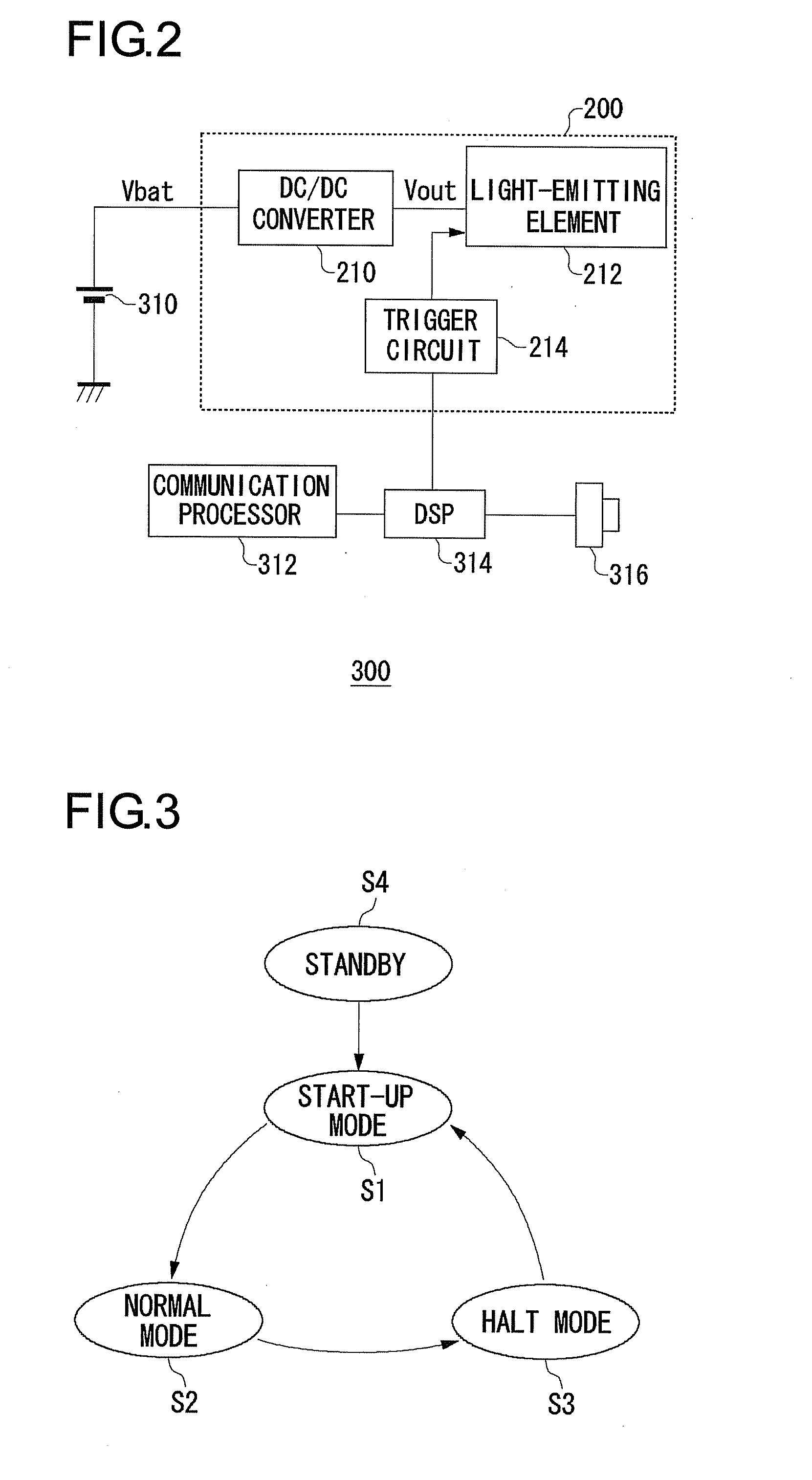
[0012]After detecting the short-circuit state and halting the switching operation of the switching transistor for a predetermined halt time, the switching controller may begin the start-up of the separately excited DC / DC converter once again. At a time of a short-circuit of the load, in cases in which a long-term short-circuit of the load is maintained, by halting the switching transistor for the predetermined halt time, since there is intermittent operation in which current flows during the start-up time and is shut off during the halt time, it is possible to prevent a large current flowing continuously in the switching transistor or transformer.
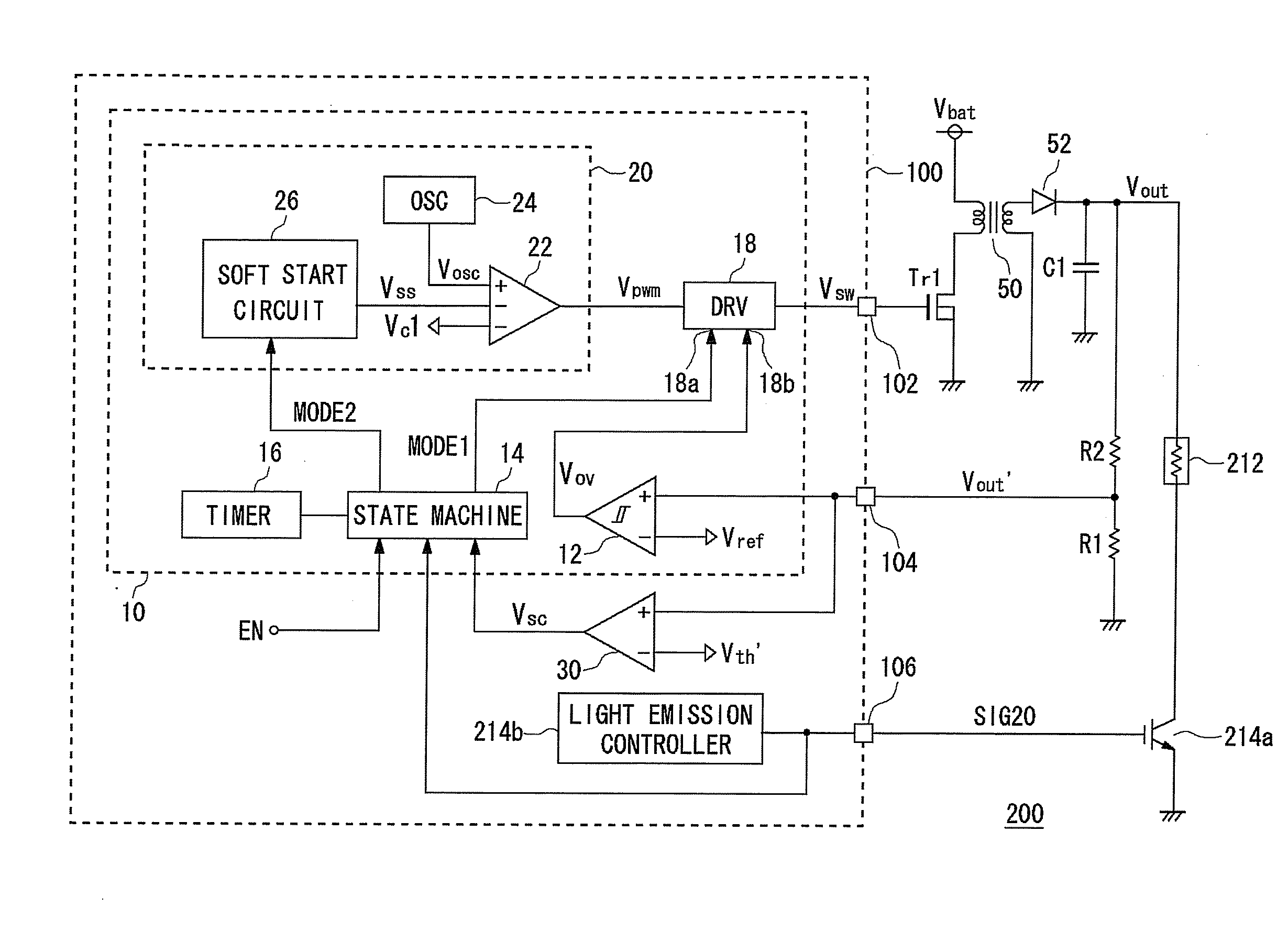
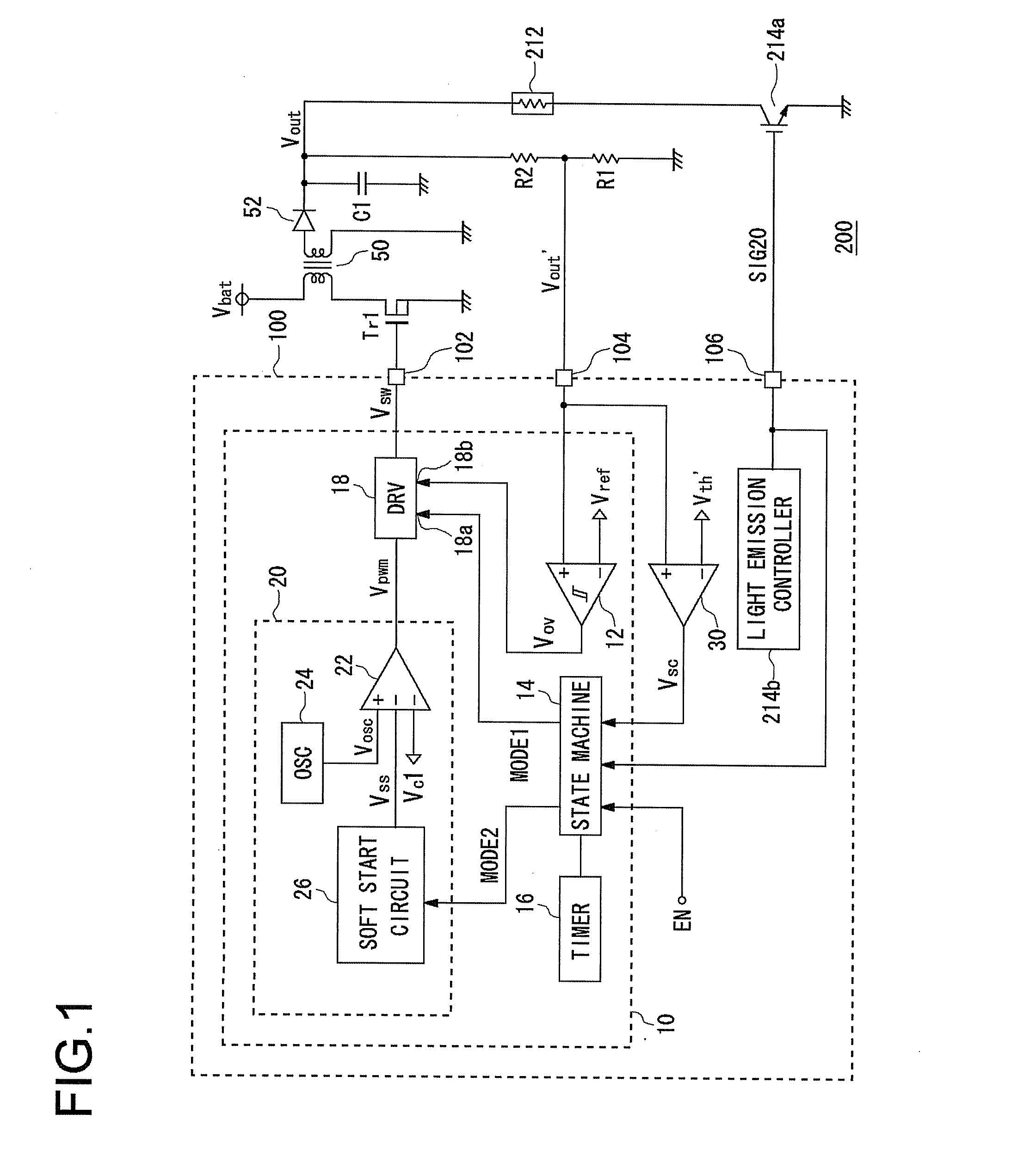
[0018]The switching controller may include a pulse width modulator which generates a pulse
signal, a
driver circuit which drives the switching transistor based on a pulse
signal, and a
hysteresis comparator which compares the output voltage and a
threshold voltage set in a vicinity of a target value of the output voltage. The pulse width modulator may gradually change a duty ratio of the pulse
signal in the start-up mode, and, in the
normal mode and the halt mode, may fix the duty ratio of the pulse signal at a predetermined value; and the
driver circuit may drive the switching transistor based on the pulse signal in the start-up mode and the
normal mode, and may halt driving of the switching transistor in the halt mode.
[0019]In such cases, it is possible to execute a soft start in the start-up mode. In addition, in the
normal mode, since the switching transistor is driven at the fixed duty ratio, irrespective of the output voltage, the output voltage gradually increases. After that, when the output voltage reaches a first
threshold voltage of the
hysteresis comparator, the switching transistor is halted, and the output voltage gradually decreases. When the output voltage decreases to a second threshold voltage of the
hysteresis comparator, driving of the switching transistor is restarted. As a result, in the normal mode, the output voltage is stabilized between the first threshold voltage and the second threshold voltage. Furthermore, by putting the
machine into a halt mode when there is a short-circuit, a step-up operation can be halted and the circuit protected.
[0024]According to this embodiment, it is possible to preferably protect the switching transistor and the transformer of the separately excited DC / DC converter from overcurrent.
[0026]According to this embodiment, when the light-emitting element, which is a load, is driven normally without a short-circuit or the like occurring, it is possible to stably emit light from the light-emitting element, and in cases of a short-circuit, it is possible to protect the circuit from overcurrent.
[0028]According to this embodiment, in cases in which the light-emitting element, which is connected to the power supply apparatus as a load, short-circuits, it is possible to prevent a large current from flowing out continuously for a long time from the battery, and it is possible to curtail
heat generation in the electronic device.

