Antenna array and antenna

An antenna array and antenna technology, which is applied in the direction of antenna array, antenna, antenna coupling, etc., can solve the problems of large installation space and enlarged antenna width, and achieve the effects of reducing coupling, increasing gain, and realizing beam width

Active Publication Date: 2017-05-24
COMBA TELECOM TECH (GUANGZHOU) CO LTD +1
View PDF5 Cites 11 Cited by
  • Summary
  • Abstract
  • Description
  • Claims
  • Application Information

AI Technical Summary

Problems solved by technology

In the existing technology, in order to reduce the width of the antenna radiation beam and increase the gain, the method of enlarging the horizontal spacing of the antenna radiation elements is generally adopted, which is intuitively manifested as the increase in the width of the antenna and the large installation space occupied

Method used


Image

  • Antenna array and antenna
  • Antenna array and antenna
  • Antenna array and antenna

Examples


Embodiment Construction

[0031] Embodiments of the present invention are described in detail below, examples of which are shown in the drawings, wherein the same or similar reference numerals designate the same or similar elements or elements having the same or similar functions throughout. The embodiments described below by referring to the figures are exemplary only for explaining the present invention and should not be construed as limiting the present invention.

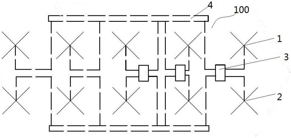
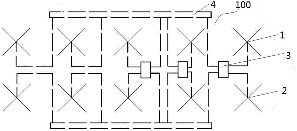
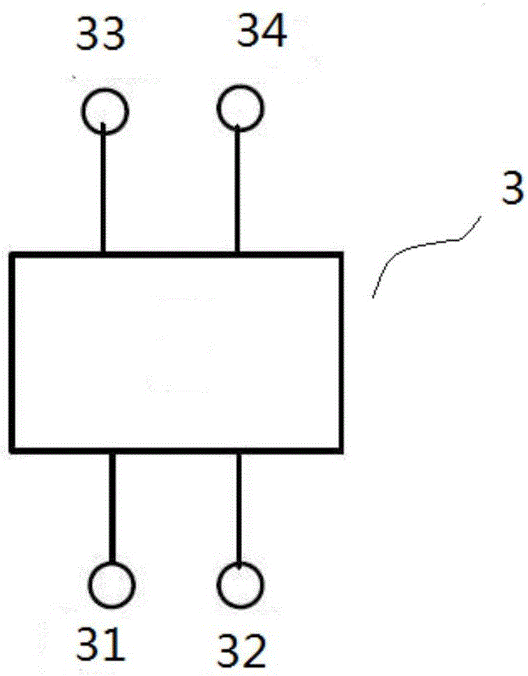
[0032] Figure 1 to Figure 3 Together, it shows that the antenna array 100 of the present invention can be applied to the base station antenna of the MIMO system to increase the system capacity. The base station antenna using the antenna array 100 can narrow the physical size of the antenna while ensuring the narrowing of the antenna beam, thereby ensuring the normal coverage of the antenna.

[0033] The antenna array 100 includes a first column element (unlabeled, the same below) and a second column element (unlabeled, the same below) ...


PUM


Abstract

The invention provides an antenna array and an antenna. The antenna array comprises first column elements and second column elements which are arranged side by side. The first column elements comprise at least one first radiation unit. The second column elements comprise at least one second radiation unit. The antenna array also comprises at least one microwave network. The microwave network is provided with two input port and two output ports. The two input ports are mutually isolated and accessed to a feed phase shift network. The two output ports are respectively connected with the first and second radiation units in the same horizontal direction, and the signals of which the range of the phase difference value is between +/-45 degrees can be outputted to the first and second radiation units at the two output ports when the electric signals are inputted from any one input port of the microwave network. With application of the scheme, narrowing of wave beam width can be realized when the physical size of the antenna is narrowed so that the gain of the antenna can be enhanced, and the miniaturization design of the antenna can be realized.

Description

technical field [0001] The present invention relates to the technical field of mobile communication, in particular, the present invention relates to an antenna array and an antenna using the antenna array. Background technique [0002] With the gradual acceleration of 4G mobile communication network deployment, in order to realize the improvement of system capacity, the current general implementation means is MIMO (Multiple-Input Multiple-Output, Multiple-Input Multiple-Output) system. In the prior art, in order to reduce the width of the antenna radiation beam and increase the gain, the method of enlarging the horizontal spacing of the antenna radiation elements is generally adopted, which intuitively shows that the width of the antenna becomes larger and occupies a larger installation space. [0003] However, with the limitation of station building space and the increasing difficulty of property coordination, the demand for miniaturization has become the development trend ...

Claims


Application Information

Patent Timeline
Patent Type & Authority Applications(China)
IPC IPC(8): H01Q21/00H01Q19/10H01Q1/52H01Q1/50
CPCH01Q1/523H01Q19/106H01Q21/0006
Inventor 贾飞飞
Owner COMBA TELECOM TECH (GUANGZHOU) CO LTD
Why Eureka
Try Eureka