Electromagnetic rack pushing type safety braking device of lifting device

A technology of lifting equipment and safety braking, which is applied to elevators, hoisting devices, transportation and packaging, etc., and can solve problems such as failure and reduced braking force

Active Publication Date: 2017-05-31
廖忠民
View PDF6 Cites 0 Cited by
  • Summary
  • Abstract
  • Description
  • Claims
  • Application Information

AI Technical Summary

Problems solved by technology

[0002] The safety braking measures of the existing rack and pinion lifting equipment are either by braking the motor shaft, or by braking the gear shaft, or by braking the shaft of the intermediate transmission link. These methods actually Braking is achieved by using friction braking to stop the gear from rotating; friction braking may cause the braking force to decrease or even fail due to friction material wear or oil pollution; moreover, if there is a problem with the drive gear, the gear will stop Rotating to achieve braking will not produce a braking effect; therefore, in order to ensure safety, the rack and pinion lifting equipment should be equipped with reliable safety braking measures that can deal with problems including driving gears and similar safety problems; moving is a viable method

Method used


Image

  • Electromagnetic rack pushing type safety braking device of lifting device
  • Electromagnetic rack pushing type safety braking device of lifting device
  • Electromagnetic rack pushing type safety braking device of lifting device

Examples


Embodiment 1

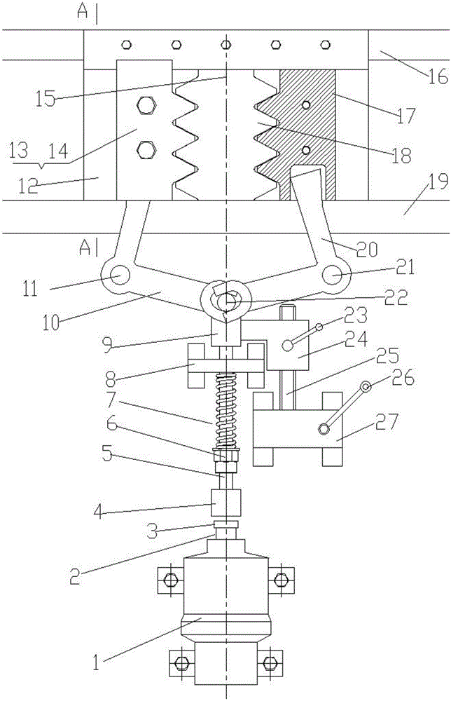
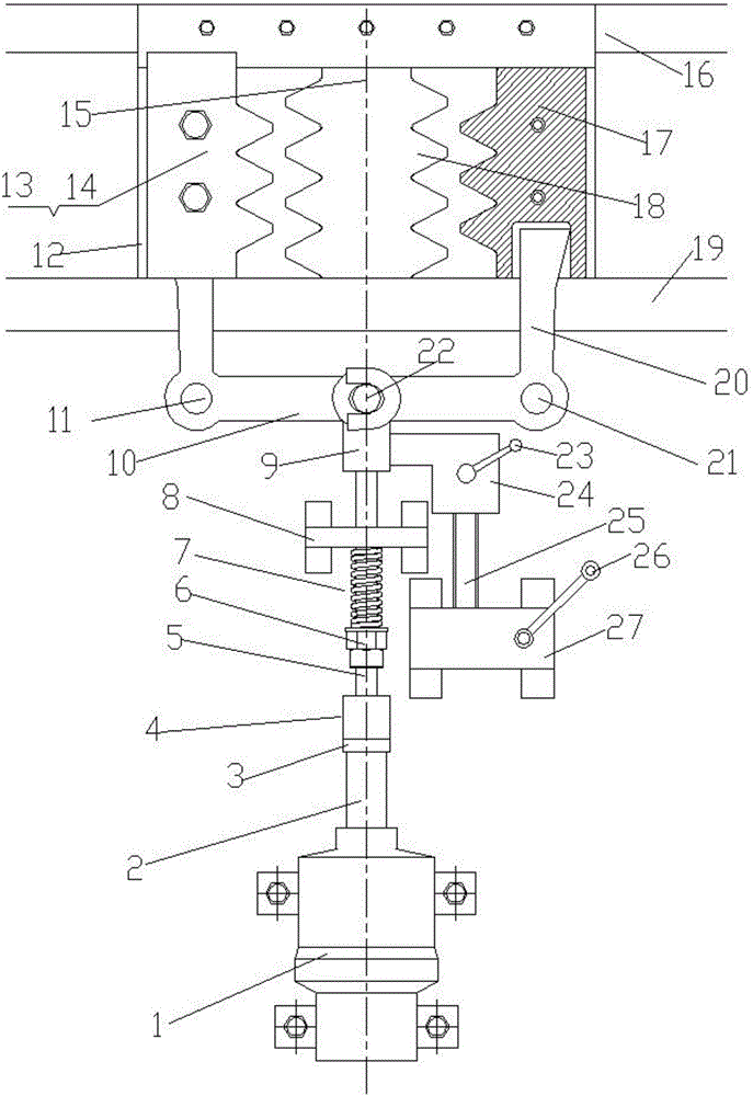
[0021] Embodiment 1, a lifting equipment equipped with an electromagnetically driven rack-type safety brake assembly directly installed on the lifting equipment car, Figure 7 It is a schematic diagram of Embodiment 1, and the drawing shows the appearance of the side of the elevator. The electromagnetically driven rack-type safety brake device is installed on the rack-and-pinion lifting equipment and is temporarily in a free position, and the lifting equipment is ready to run or is running. Condition, Figure 8 It is a schematic diagram of the situation that the electromagnetically driven rack type safety braking device of embodiment 1 brakes the lifting equipment, (the left and right described in the previous figure are viewed from the inside of the lifting equipment to the side of the lifting equipment, Figure 7 , 8 It is viewed from the outside to the side of the lifting equipment, so the left and right directions are just opposite), the electromagnetically driven rack-ty...

Embodiment 2

[0022] Embodiment 2 is a lifting device equipped with an electromagnetically driven rack-type safety brake device independent safety brake device assembly according to the present invention, Figure 9 It is a schematic diagram of embodiment 2, showing that the main body of the electromagnetic pusher 1 is in a power-off state, and the situation when the electromagnetic pusher rack type safety brake device implements braking, Figure 10 In embodiment 2, when the main body 1 of the electromagnetic pusher is in the energized state and the electromagnetically driven rack-type safety brake device is in a free position, the specific structure of the electromagnetically driven rack-type safety brake device used in the lifting equipment is a An independent safety brake device assembly that sets independent components separately and is then installed on the lifting equipment, Figure 11It is a schematic diagram of an independent safety brake assembly of the electromagnetically driven ra...

Embodiment 3

[0023] Embodiment 3, an elevator equipped with an electromagnetically propelled rack-type safety brake assembly directly installed on the elevator car, its appearance is the same as Figure 7 , Figure 8 , the working principle is the same as that described in paragraph [0021].


PUM


Abstract

The invention discloses an electromagnetic rack pushing type safety braking device of a lifting device. A movable rack is electromagnetically pushed to horizontally move on a rail or keep at certain determined positions. The top of the movable rack makes direct contact with a main bearing structure of a lifting device lift car after entering a braking state for bearing or makes contact with the main bearing structure through a middle transition bearing part for bearing. A operation mechanism for the movable rack operates the movable rack to horizontally move on a rail hole or stay and keep at certain determined positions, wherein the determined positions include a braking position engaged with a drive rack of the lifting device or a free position completely disengaged from the drive rack of the lifting device and having a certain gap with the drive rack. Electromagnetic rack pushing type safety protection braking is adopted, so that the beneficial effects that the flat layer precision is obviously improved, and the safety protection braking quality is obviously improved are achieved.

Description

technical field [0001] The invention relates to the field of safety braking devices for lifting equipment, in particular to an electromagnetically driven rack type safety braking device for lifting equipment. Background technique [0002] The safety braking measures of the existing rack and pinion lifting equipment are either by braking the motor shaft, or by braking the gear shaft, or by braking the shaft of the intermediate transmission link. These methods actually Braking is achieved by using friction braking to stop the gear from rotating; friction braking may cause the braking force to decrease or even fail due to friction material wear or oil pollution; moreover, if there is a problem with the drive gear, the gear will stop Rotating to achieve braking will not produce a braking effect; therefore, in order to ensure safety, the rack and pinion lifting equipment should be equipped with reliable safety braking measures that can deal with problems including driving gears a...

Claims


Application Information

Patent Timeline
Patent Type & Authority Applications(China)
IPC IPC(8): B66B5/26B66B1/42B66B11/04B66D5/24B66D5/30
CPCB66B1/365B66B1/42B66B5/26B66B11/0415B66D5/24B66D5/30
Inventor 廖忠民
Owner 廖忠民
Why Eureka
Try Eureka