
A sheet metal bending machine
A technology for bending machines and sheet metal parts, which is applied in the field of sheet metal parts bending machines, which can solve the problems of inconvenient bending of sheet metal parts for many times, and achieve the effects of fast bending speed, simple control and high bending strength.
Patent Information
- Authority / Receiving Office
- CN · China
- Patent Type
- Patents(China)
- Current Assignee / Owner
- Publication Date
- 2018-07-10
Smart Images
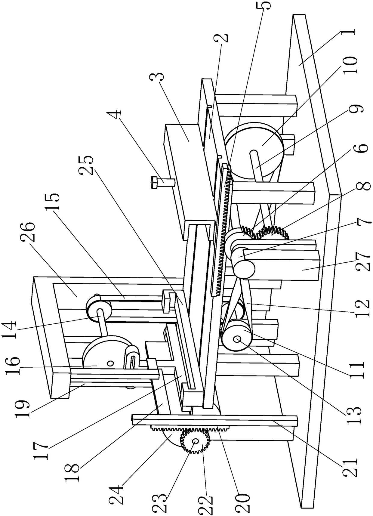
Figure 1 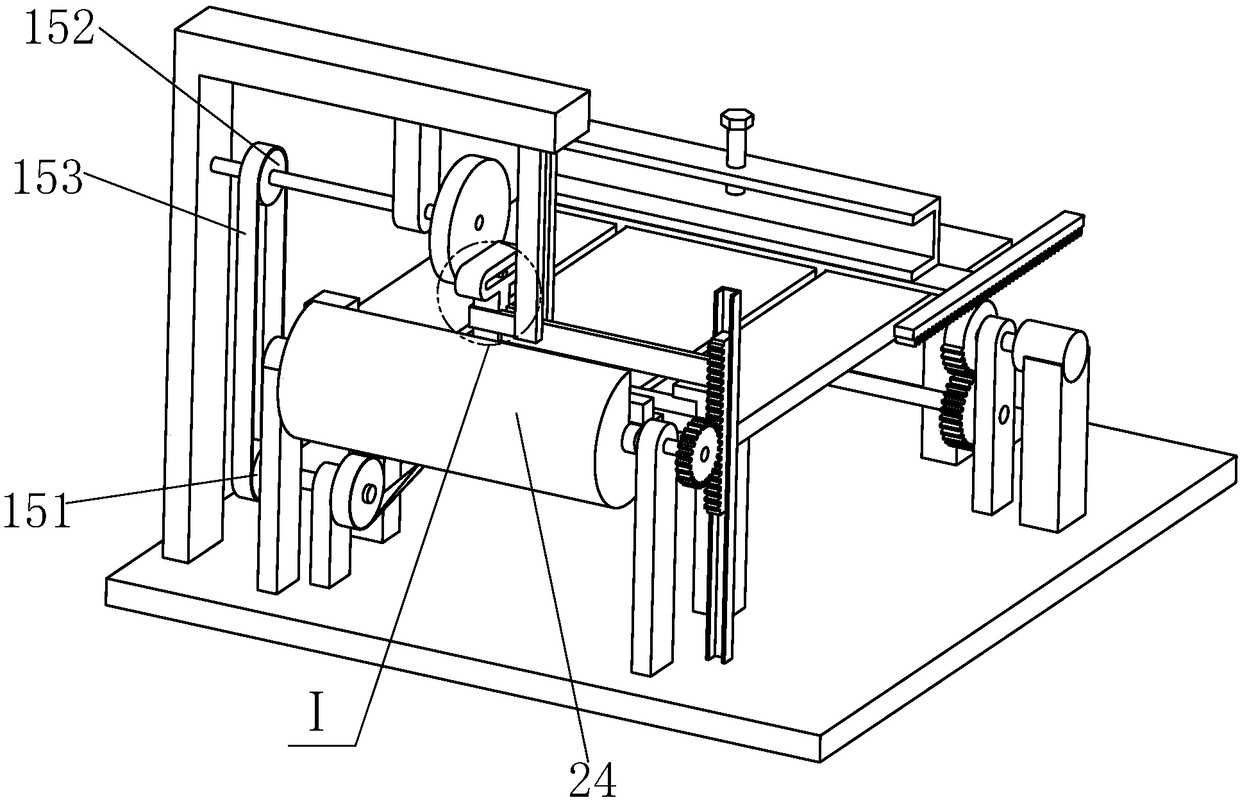
Figure 2 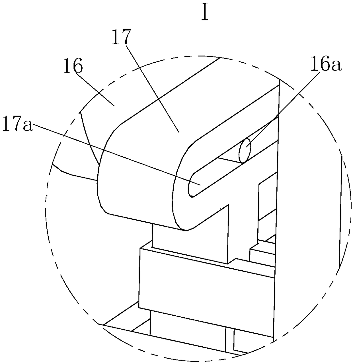
Figure 3
Abstract
Description
technical field
[0001] The invention relates to machining equipment, in particular to a bending machine for sheet metal parts. Background technique
[0002] Sheet metal parts are products processed by sheet metal technology. Sheet metal parts are processed by filament power winding, laser cutting, heavy processing, metal bonding, metal drawing, plasma cutting, precision welding, roll forming, sheet metal bending, Die forging, water jet cutting to produce. Some sheet metal parts often need to bend the flat sheet metal parts at 90 degrees multiple times according to the needs of the application field, but in the specific processing, it is necessary to manually bend the sheet metal parts after each bending. It is very inconvenient to continue to push to the bending machine to facilitate continuous bending. Contents of the invention
[0003] In order to solve the defect that it is very inconvenient to bend sheet metal parts multiple times in the above technology, the present...
Examples
Embodiment Construction
[0026] In order to make the technical means, creative features, goals and effects achieved by the present invention easy to understand, the present invention will be further elaborated below.
[0027] Such as Figure 1 to Figure 4 As shown, a bending machine for sheet metal parts includes a base plate 1 and a workbench 2 fixed on the center of the base plate 1. The upper left part of the workbench 2 is horizontally mounted with a jaw frame 3, and the jaw frame 3 Fastening bolts 4 are installed on the top, and a No. 1 rack 5 is welded to the front end of the jaw frame 3. The lower end of the No. 1 rack 5 is provided with an incomplete gear 6 corresponding to a central angle of 180 degrees. The incomplete gear 6 Adapted to the No. 1 rack 5, the incomplete gear 6 is connected with a motor 7.
[0028] The underside of the incomplete gear 6 is provided with a transmission gear 8 that is compatible with the incomplete gear 6, the circumference of the transmission gear 8 is the same...