Dry connection method of concrete slab and steel beam of steel-concrete composite beam
Active Publication Date: 2019-03-22
崔冰 +2
View PDF6 Cites 0 Cited by
Summary
Abstract
Description
Claims
Application Information
AI Technical Summary
This helps you quickly interpret patents by identifying the three key elements:
Problems solved by technology
Method used
Benefits of technology
Problems solved by technology
This connection method requires on-site pouring of concrete. There are a lot of steel bar binding, connection work and concrete pouring work. The construction period is long and environmental pollution cannot be avoided. Once the concrete slab and steel beam are connected as a whole, they cannot be disassembled and it is difficult to reuse
Method used
Image
Click on the blue label to locate the original text in one second.
Reading with bidirectional positioning of images and text.
Examples
Embodiment 1
[0035] The first specific embodiment of the present invention is a method for connecting a concrete slab and a steel beam of a steel-concrete composite beam, the steps of which are:
[0036] A method for dry connection of a concrete slab and a steel beam of a steel-concrete composite beam, the steps of which are:
[0037] A. Production of positioning templates
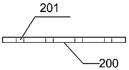
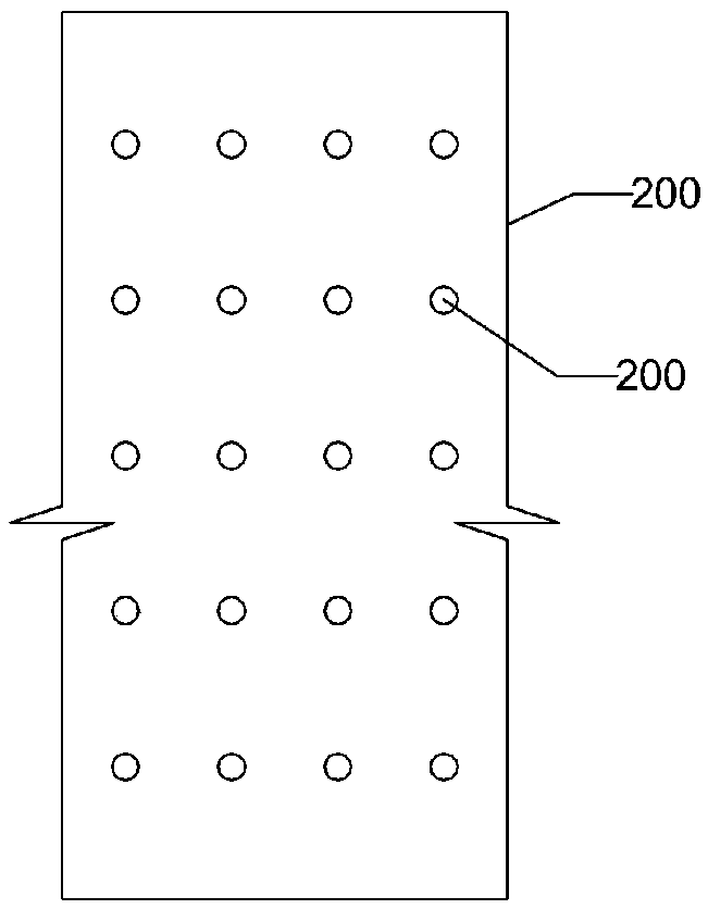
[0038] On the steel plate with the same width as the upper flange plate 400 of the steel beam, the positioning holes 201 are drilled according to the spacing of the connecting rods 103 of the steel-concrete composite beam to form a positioning template 200; see Figure 1a , Figure 1b and image 3 .
[0039] B. Production of steel plate connectors
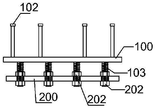
[0040] Welding the lower end of the shear connector 102 to the upper surface of the connecting plate 100 having the same width as the upper flange plate 400 of the steel beam;
[0041] Insert the connecting rod 103 into the positioning hole of the positioning template 2...
Embodiment 2
[0049] The second specific embodiment of the present invention is a method for connecting a concrete slab and a steel beam of a steel-concrete composite beam, the steps of which are:
[0050] A. Production of positioning templates
[0051] On the steel plate with the same width as the upper flange plate 400 of the steel beam, the positioning holes 201 are drilled according to the spacing of the connecting rods 103 of the steel-concrete composite beam to form the positioning template 200;
[0052] B. Production of steel plate connectors
[0053] Welding the lower end of the shear connector 102 to the upper surface of the connecting plate 100 having the same width as the upper flange plate 400 of the steel beam;
[0054]Insert the connecting rod 103 into the positioning hole of the positioning template 200, fix the connecting rod 103 and the positioning template 200 with a temporary fastener 202, then fix the connecting rod 103 to the lower surface of the connecting plate 100, ...
Embodiment 3
[0062] A third embodiment of the present invention is a method for connecting a concrete slab of a steel-concrete composite beam to a steel beam, the steps of which are:
[0063] A method for dry connection of a concrete slab and a steel beam of a steel-concrete composite beam, the steps of which are:
[0064] A. Production of positioning templates
[0065] On the steel plate with the same width as the upper flange plate 400 of the steel beam, the positioning holes 201 are drilled according to the spacing of the connecting rods 103 of the steel-concrete composite beam to form the positioning template 200;
[0066] B. Production of steel plate connectors
[0067] Welding the lower end of the shear connector 102 to the upper surface of the connecting plate 100 having the same width as the upper flange plate 400 of the steel beam;
[0068] Insert the connecting rod 103 into the positioning hole of the positioning template 200, fix the connecting rod 103 and the positioning temp...
PUM
Abstract
A dry connection method for a concrete slab of a steel-concrete composite beam and a steel beam, the steps of which are: A, making a positioning template; B, making a steel plate connector: welding the lower end of the shear connector to the connecting plate surface; insert the connecting rod into the positioning hole of the positioning template, temporarily fix the connecting rod and the positioning template, and then fix the connecting rod with the lower surface of the connecting plate, then remove the temporary fixation, and remove the positioning template; C, steel plate connection The connection between the device and the concrete slab: pre-embed the shear connector in the concrete slab; and expose the connecting rod and the connecting slab; D. The connection between the concrete slab and the steel beam: clamp the positioning formwork on the upper flange of the steel beam, and The position of the positioning hole of the positioning template is drilled to connect the through hole; the positioning template is removed; the connecting rod is inserted into the connecting through hole, and finally the connecting rod is fixed on the lower surface of the upper flange plate of the steel beam to form a steel-concrete composite beam. The method can reduce the site construction amount and environmental pollution, and accelerate the construction speed.
Description
technical field [0001] The invention belongs to a method for connecting a concrete slab and a steel beam of a steel-concrete composite beam. Background technique [0002] Steel-concrete composite beam is a new type of structure developed on the basis of steel structure and concrete structure. It resists the lifting and relative sliding of the two at the interface by setting shear connectors (bolts, channel steel, bending bars, etc.) between the lower steel beam and the upper concrete flange (concrete slab) , so that the steel beam and the concrete slab work together as a beam that works as a whole. In the steel-concrete composite beam, the existing connection method between the steel beam and the concrete slab is: one end of the shear connector is welded to the steel beam on site, and the rest of the shear connector is poured into the concrete slab, so that the steel beam Connected to the concrete slab as a whole. This connection method requires on-site pouring of concret...
Claims
Application Information
Patent Timeline
Application Date:The date an application was filed.
Publication Date:The date a patent or application was officially published.
First Publication Date:The earliest publication date of a patent with the same application number.
Issue Date:Publication date of the patent grant document.
PCT Entry Date:The Entry date of PCT National Phase.
Estimated Expiry Date:The statutory expiry date of a patent right according to the Patent Law, and it is the longest term of protection that the patent right can achieve without the termination of the patent right due to other reasons(Term extension factor has been taken into account ).
Invalid Date:Actual expiry date is based on effective date or publication date of legal transaction data of invalid patent.

