A motor built-in gear pump
A built-in, gear pump technology, applied in the field of oil pumps and gear pumps, can solve the problems of shaft vibration, large volume of oil pumps, high coaxiality requirements, etc., and achieve the effect of avoiding energy loss, more compact structure, reasonable and perfect structure
- Summary
- Abstract
- Description
- Claims
- Application Information
AI Technical Summary
Problems solved by technology
Method used
Image

Examples
Embodiment 1
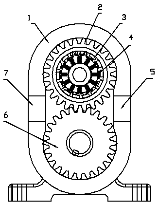
[0012] Embodiment 1: as figure 1 As shown, a pair of rotary gears are installed in the pump body 1 of the oil pump, one is the active rotary gear 2, and the other is the passive rotary gear 6. The two rotary gears mesh with each other, and the entire working chamber in the pump is divided into two independent parts. A is the suction chamber 5, and B is the discharge chamber 7. When the gear oil pump is in operation, the active rotary gear 2 drives the passive rotary gear 6 to rotate.
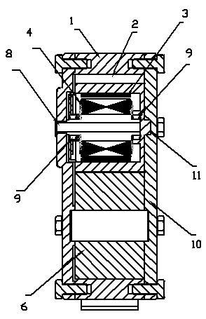
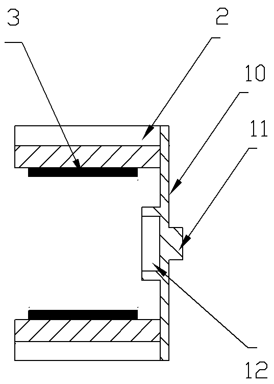
[0013] Such as figure 2 , 3 As shown, the side body of the pump body 1 is provided with a non-penetrating shaft hole, the driving rotary gear 2 is tubular, and the side is closed with a side plate 10 to make it a barrel shape. The outer central axis of the side plate 10 is provided with The protruding shaft 11 is used as a fulcrum, so that it can cooperate with the non-penetrating shaft hole on the inner wall of the pump body 1 shell to become a fulcrum of rotation. The inner side of the side...
Embodiment 2
[0017] Embodiment 2: as Figure 5 As shown, a pair of rotary gears are installed in the pump body 1 of the oil pump, one is the active rotary gear 2, and the other is the passive rotary gear 6. The two rotary gears mesh with each other, and the entire working chamber in the pump is divided into two parts—suction Chamber 5 and discharge chamber 7, when the gear oil pump is running, the active rotary gear 2 drives the passive rotary gear 6 to rotate.
[0018] A shaft hole is arranged on the side of the pump body 1 corresponding to the driving rotary gear 2, and the shaft hole is used for fixing and installing the motor shaft 8.
[0019] The inner cavity of the driving rotary gear 2 is processed into a barrel shape, the bottom wall is provided with a shaft hole, and the magnetic steel 3 is pasted on the peripheral wall of the inner cavity, and the rotating shaft of the motor passes through the shaft hole of the bottom wall of the driving rotary gear 2, and is connected to the pum...
PUM
 Abstract
Description
Claims
Application Information
 - R&D
- Intellectual Property
- Life Sciences
- Materials
- Tech Scout
- Unparalleled Data Quality
- Higher Quality Content
- 60% Fewer Hallucinations
Browse by: Latest US Patents, China's latest patents, Technical Efficacy Thesaurus, Application Domain, Technology Topic, Popular Technical Reports.
© 2025 PatSnap. All rights reserved.Legal|Privacy policy|Modern Slavery Act Transparency Statement|Sitemap|About US| Contact US: help@patsnap.com