Power detection device of laser device

A technology of power detection and laser power, applied in the direction of using electric radiation detectors for photometry, etc., can solve the problems of deviation of detection data, high production cost, inaccurate detection results, etc., to reduce energy loss, improve detection accuracy, reduce energy effect

Active Publication Date: 2017-10-20
WENZHOU FIBER LASER
View PDF5 Cites 3 Cited by
  • Summary
  • Abstract
  • Description
  • Claims
  • Application Information

AI Technical Summary

Problems solved by technology

[0002] The rated power of the semiconductor laser is an important indicator of the laser process parameters. Only the appropriate laser power can ensure the stable operation of the laser and the optical system for a long time, and it is also the decisive factor for achieving the best processing quality. In the existing laser detection methods, generally By selecting a lighting sheet, a small part of the laser light is reflected to the laser detector, and the linear relationship in the laser detection is prevented from interfering with strong light through the amplification effect. In the existing technology, it is generally selected to filter other stray light and pass through The light-transmitting plate with 1% laser reflects the intercepted less than 1% of the laser light into the laser detector to avoid the interference of other strong light. Due to the high technical requirements of the light-transmitting plate, the equipment manufacturing cost is high, and its The surface of the light-transmitting plate splits the light through the coating or the arrangement angle of the prisms. The coating tends to decrease steadily under long-term laser irradiation. In addition, the prism needs to be installed at a specific angle to split the laser light. The angle has high precision requirements. When determining the laser interception rate, repeated trials are required to determine the installation angle. When in use, both the laser head and the prism are prone to offset, resulting in a change in the laser interception rate, which in turn leads to inconsistent detection results. Inaccurate, which leads to low stability of the light-transmitting plate, and it is easy to cause deviations in the detection data when the stability of the light-transmitting plate decreases, and it does not have self-test capability

Method used


Image

  • Power detection device of laser device
  • Power detection device of laser device
  • Power detection device of laser device

Examples


Embodiment Construction

[0031] The present invention will be described in further detail below in conjunction with the embodiments given in the accompanying drawings.

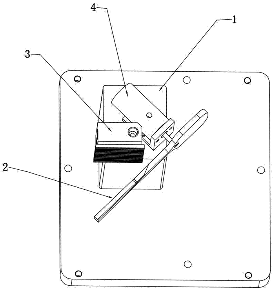
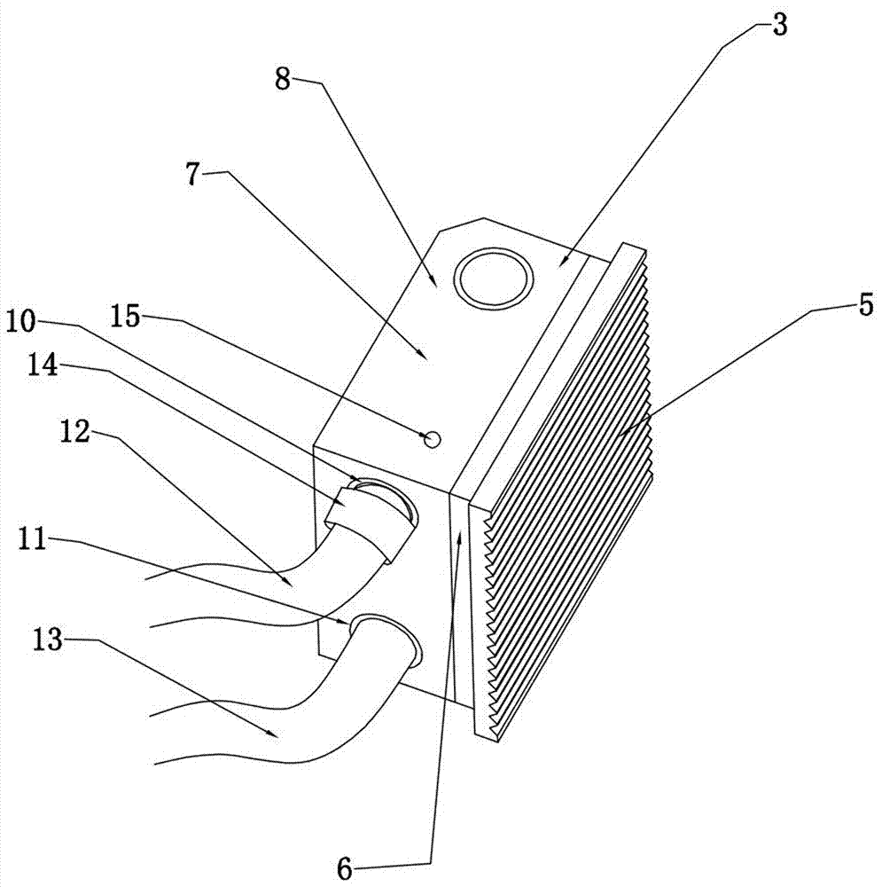
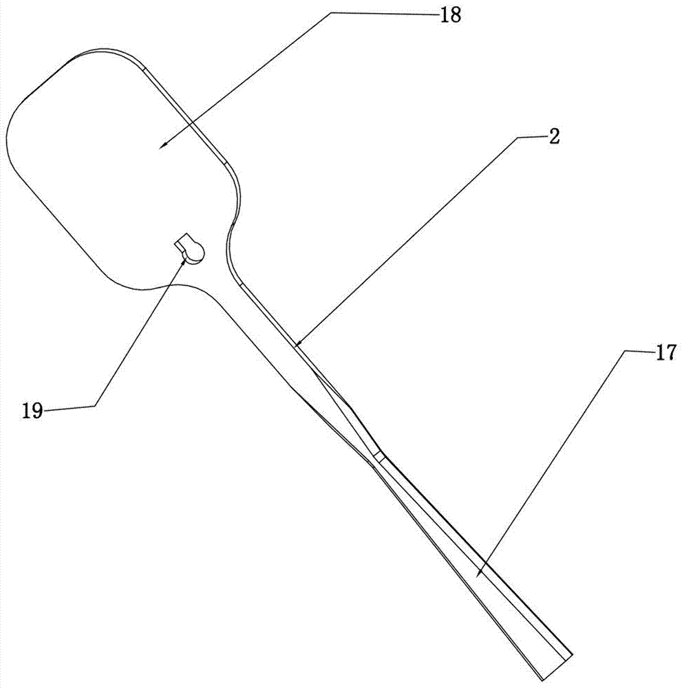
[0032] refer to Figure 1-6 As shown, a laser power detection device disclosed in this embodiment includes a power detection assembly 1, the power detection assembly 1 includes a reflector 2 and a laser power detector 3, and the reflector 2 reflects the laser light emitted by the laser The power is detected on the laser power detector 3 , and the reflector 2 periodically reflects the laser beam of the laser, so that the laser power detector 3 periodically receives the laser light reflected by the reflector 2 .

[0033]The reflective plate 2 has better stability relative to the light-transmitting plate. The reflective plate 2 is arranged in front of the laser emitting light path. The angles between them are equal, so that the beam path can be accurately projected onto the receiving surface of the laser detection component through the ...


PUM


Abstract

The invention discloses a power detection device of a laser device. The power detection device comprises a power detection component which is composed of a light reflecting plate and a laser power detector. The light reflecting plate reflects the laser emitted by the laser device to the laser power detector to perform power detection. The light reflecting plate periodically reflects the laser beams of the laser device so that the laser power detector is enabled to periodically receive the laser reflected by the light reflecting plate. The power detection device of the laser device has low production cost, high detection value stability and high accuracy.

Description

technical field [0001] The invention relates to the field of laser detection equipment, in particular to a laser power detection device. Background technique [0002] The rated power of the semiconductor laser is an important indicator of the laser process parameters. Only the appropriate laser power can ensure the stable operation of the laser and the optical system for a long time, and it is also the decisive factor for achieving the best processing quality. In the existing laser detection methods, generally By selecting a lighting sheet, a small part of the laser light is reflected to the laser detector, and the linear relationship in the laser detection is prevented from interfering with strong light through the amplification effect. In the existing technology, it is generally selected to filter other stray light and pass through The light-transmitting plate with 1% laser reflects the intercepted less than 1% of the laser light into the laser detector to avoid the interf...

Claims


Application Information

Patent Timeline
Patent Type & Authority Applications(China)
IPC IPC(8): G01J1/42
CPCG01J1/42
Inventor 程国军余勤跃扈金富
Owner WENZHOU FIBER LASER
Why Eureka
Try Eureka