Convenient electric power device

A kind of electric equipment, convenient technology, applied in the direction of electrical components, switchgear, pull-out switchgear, etc., can solve the problems of power distribution cabinet tilting forward, power distribution cabinet overturning, loss, etc., to achieve simple structure of the device, Increased safety and stable operation

Inactive Publication Date: 2017-12-05
广州冠松电力科技有限公司
View PDF4 Cites 1 Cited by
  • Summary
  • Abstract
  • Description
  • Claims
  • Application Information

AI Technical Summary

Problems solved by technology

[0002] The power distribution cabinet is a cabinet used to install and protect power components. It is a common equipment in power facilities. In order to facilitate the installation, maintenance and classification of power components, the power distribution cabinet is usually set into a drawer type. , it is often necessary to pull out the drawer during installation or maintenance. When the drawer is pulled out, the center of gravity of the power distribution cabinet will be moved forward. When the power components in the drawer are heavy, the power distribution cabinet will be tilted forward. Serious It will cause the power distribution cabinet to fall forward and crush people, resulting in heavy losses. Therefore, the traditional power distribution cabinet has potential safety hazards

Method used


Image

  • Convenient electric power device
  • Convenient electric power device
  • Convenient electric power device

Examples


Embodiment Construction

[0021] All features disclosed in this specification, or steps in all methods or processes disclosed, may be combined in any manner, except for mutually exclusive features and / or steps.

[0022] Any feature disclosed in this specification (including any appended claims, abstract and drawings), unless expressly stated otherwise, may be replaced by alternative features which are equivalent or serve a similar purpose. That is, unless expressly stated otherwise, each feature is one example only of a series of equivalent or similar features.

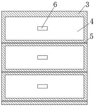
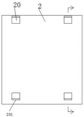
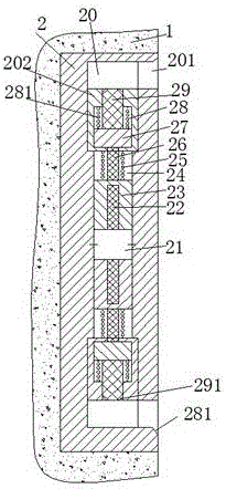
[0023] like Figure 1-5 As shown, a convenient electric device of the present invention includes a fixing frame 2 fixedly installed in a wall 1 and a power distribution cabinet 3, and the power distribution cabinet 3 includes a plurality of drawers 4 that can be pulled back and forth, Each of the drawers 4 is separated by a partition 5, and each of the drawers 4 is provided with a handle 6 on the front surface, and the handle 6 is used to fac...


PUM


Abstract

A convenient electrical equipment, comprising a fixing frame fixedly installed in the wall and a power distribution cabinet, the power distribution cabinet includes a plurality of drawers that can be pulled back and forth, and each of the drawers is separated by a partition , and each of the drawers is provided with a handle on the front surface, and the fixing frame is provided with a fixing member corresponding to the left and right, and the fixing member includes a first sliding groove extending up and down and a first sliding groove located at the upper and lower ends of the first sliding groove The second sliding groove, each second sliding groove is provided with a mouth protruding hole facing the front end, a motor is fixedly installed at the midpoint of the first sliding groove, and a screw rod is connected to the upper and lower ends of the motor, so The first slide groove is located on the upper and lower sides of the motor, and the first slide block is installed in a slidable manner. The first slide block is provided with an inner screw hole matching the screw rod. The power distribution cabinet The back of the body is provided with a connecting member matched with the insertion hole.

Description

technical field [0001] The invention relates to the field of electric facilities, in particular to convenient electric equipment. Background technique [0002] The power distribution cabinet is a cabinet used to install and protect power components. It is a common equipment in power facilities. In order to facilitate the installation, maintenance and classification of power components, the power distribution cabinet is usually set into a drawer type. , it is often necessary to pull out the drawer during installation or maintenance. When the drawer is pulled out, the center of gravity of the power distribution cabinet will be moved forward. When the power components in the drawer are heavy, the power distribution cabinet will be tilted forward. Serious It will cause the power distribution cabinet to fall forward and crush people, thereby causing heavy losses. Therefore, the traditional power distribution cabinet has potential safety hazards. Contents of the invention [00...

Claims


Application Information

Patent Timeline
Patent Type & Authority Applications(China)
IPC IPC(8): H02B11/127
CPCH02B11/127
Inventor 袁承宇
Owner 广州冠松电力科技有限公司
Why Eureka
Try Eureka