

Nanometer mirror
A nano-mirror technology, applied in the field of nano-mirror, can solve the problem of non-adjustable anti-fog, achieve good lighting conditions and prevent fogging
- Summary
- Abstract
- Description
- Claims
- Application Information
AI Technical Summary
Problems solved by technology
Method used
Image

Examples
Embodiment Construction
[0021] In order to make the object, technical solution and advantages of the present invention more clear, the present invention will be further described in detail below in conjunction with the accompanying drawings and embodiments. It should be understood that the specific embodiments described here are only used to explain the present invention, not to limit the present invention.
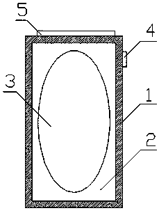
[0022] refer to figure 1 As shown, one embodiment of the present invention, a kind of nano mirror, comprises frame body 1, is provided with glass 2 in above-mentioned frame body 1, and above-mentioned glass 2 surface is provided with nanometer hydrophilic layer 3, and above-mentioned nanometer hydrophilic layer 3 surface is Nano-titanium dioxide film, the surface contact angle of the above-mentioned nano-titanium dioxide film is 1-30 degrees, by installing glass 2 in the frame body 1, preventing water molecules from contacting the glass 2 through the nano-hydrophilic layer 3 on the surface of th...
PUM
| Property | Measurement | Unit |
|---|---|---|
| contact angle | aaaaa | aaaaa |
| contact angle | aaaaa | aaaaa |
| contact angle | aaaaa | aaaaa |
Abstract
Description
Claims
Application Information